This thread has been locked.

If you have a related question, please click the "Ask a related question" button in the top right corner. The newly created question will be automatically linked to this question.

OMAPL137 EDMA SPI ARM

Other Parts Discussed in Thread: OMAPL138

Hi,

I have been trying to figure how to do spi over edma on the omapl137. I started from the Starterware examples for the omapl138 and have been able to succesfully run spi with and without edma on the dsp as well as spi without edma on the arm. When trying to test my code for spi with edma on the arm the code gets stuck in:

the first write enable:

/* Wait until both the flags are set to 1 in the callback function. */
while((0 == flagTx) || (0 == flagRx));

I have reviewed everything I have been able to find in the documentation and in the forums:

  1. completion interrupt is being set in region 0 for the arm and 1 for the dsp (the driver is taking care of it correctly)
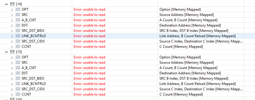
  2. i have modified the Edma3Request Channel for SPI0 channels to 15 and 14 for TX and RX respectively.
  3. the code initializes and seems to work OK for the UARTSTDIO
  4. pinmux for the dsp and arm is the same (DSP with edma is working)
  5. I have moved, per one of your forums, the ARM code to different memory location. One of your forums stated that edma does not have access to 0x80000000.
  6. I'm setting the suspend
    // Configure UART2 with the ARM CPU
    CSL_FINST(sysRegs->SUSPSRC, SYSCFG_SUSPSRC_SPI0SRC, ARM);
    Tthis work on spi0 arm without edma.

Any suggestions will be appreciated. The fact that I have the arm working without edma and the dsp with edma tells me I'm close but I'm not sure what else to test.

I have another  thread that went stale but that I requested to close since I figured out the original question (running arm without edma) 

  • I also have the code isolated in separate folder an have run beyond compare to make sure the pieces that are common are equal between the projects.
  • Hi
    few more things to check - even though it may not help if you have got OMAPL138 EDMA w/ ARM working
    1) EDMA completion interrupt to AINTC mapping. Have you confirmed that you are using the right interrupt number (#11) EDMA3_CC0_CCINT?
    2) What is your source/destination buffers for EDMA transfers to/from SPI? Share the address
    3) In Step 5 you say that EDMA cannot access 0x8000 0000, that is not true, that address is the location of Shared RAM and EDMA can access this location. Refer to Table 3-4 in the datasheet, and look for the EDMA column for all memory addresses accessible by EDMA.
    4) When the execution is stuck at the while loop, can you look at the PARAM for channel 14 and 15 , and see if they have changed any? If the param values have not changed that means you have not got the spi rx/tx event, if they have changed , you may have some programming or addressing error?

    Regards
    Mukul
  • Hi Mukul,

    Thanks for the quick reply. Please be aware that I'm trying to run these experiments on an omapl137 not the omapl138. I'm using the omapl138 as a reference. With that in mind, as I said before, I have 3 of the examples running succesfully in the omapl137 but the spi edma version.

    1) EDMA completion interrupt to AINTC mapping. Have you confirmed that you are using the right interrupt number (#11) EDMA3_CC0_CCINT?

    Yes it is 11. Thanks for the tip. I just checked: SYS_INT_CCINT0 in my header file and it is equal to 11.

    This part of the code takes care of registering the interrupt:

    IntRegister(SYS_INT_CCINT0, Edma3ComplHandlerIsr);

    IntChannelSet(SYS_INT_CCINT0, 2);

    IntSystemEnable(SYS_INT_CCINT0);

    2) What is your source/destination buffers for EDMA transfers to/from SPI? Share the address

    In this case, since I'm trying to isolate the issue on the tx side. 

    /* Configure the PaRAM registers in EDMA for Transmission.

    SpiTxEdmaParamSet(EDMA3_CHA_SPI0_TX, EDMA3_CHA_SPI0_TX, &writeEn, buffLength);

    writeEn unsigned char . 0x118057A8

    /* srcAddr holds address of memory location buffer. */
    paramSet.srcAddr = (unsigned int) buffer;

    /* destAddr holds address of SPIDAT1 register. */
    paramSet.destAddr = (unsigned int) (SOC_SPI_0_REGS + SPI_SPIDAT1);

    /** @brief Base address of SPI memory mapped registers */

    #define SOC_SPI_0_REGS (0x01C41000u) + #define SPI_SPIDAT1 (0x3C) this matches the datasheet.

    3) In Step 5 you say that EDMA cannot access 0x8000 0000, that is not true, that address is the location of Shared RAM and EDMA can access this location. Refer to Table 3-4 in the datasheet, and look for the EDMA column for all memory addresses accessible by EDMA. 


    Thanks for the note, I was referring to the following thread. Towards the end. 

    4) When the execution is stuck at the while loop, can you look at the PARAM for channel 14 and 15 , and see if they have changed any? If the param values have not changed that means you have not got the spi rx/tx event, if they have changed , you may have some programming or addressing error?

    Let me answer this in a bit to save my first response.

  • 4) When the execution is stuck at the while loop, can you look at the PARAM for channel 14 and 15 , and see if they have changed any? If the param values have not changed that means you have not got the spi rx/tx event, if they have changed , you may have some programming or addressing error?

    Thanks for the  suggestion. As I step into the code I can see that the PARAM for 14 and 15 have not change. They remain at zero.

    but I confuse about your suggestion. Shouldn't the values resemble what I have configure in the following function?

    /* Now write the PaRam Set to EDMA3.*/
    EDMA3SetPaRAM(SOC_EDMA3CC_0_REGS, chNum, &paramSet);

  • Hmm.. unless you are poking the wrong values in param, param should indeed be programmed to what you are trying to set it to.
    If you have your DSP EDMA based program handy for OMAPL137, try to poke the same addresses before you trigger the transfer (but after you have programmed the PARAM) , to see if you are seeing the desired values. If so, you are probably missing something in your ARM side program.

    If you have a linker command file, i would recommend keeping all your data, text etc in Shared RAM space or external memory etc. Also compare and contrast your linker command file for the working OMAPL138 ARM/EDMA example vs OMAPL137 ARM/EDMA non working example

    The post you pointed was for 0x0080 0000 location (DSP internal memory local address) , not 0x8000 0000 location (Shared RAM). If you are using DSP memory for EDMA source/destination , yes make sure that the linker command file uses the "global" address i.e. 0x118x xxxx.
  • Thanks for the suggestions:

    I have change my linker to point the code to Shared RAM.

    SHRAM        o = 0x80000000  l = 0x00020000  /* 128kB Shared RAM */

    both arm and dsp have their code mapped to Shared RAM and the DSP continues to work.

    One interesting thing I see is: I cannot access those registers for the EDMA CC on the DSP but I can for the ARM. I have a break point in the exact same location.

    Right after the following call:

    /* Configure the PaRAM registers in EDMA for Transmission. */
    SpiTxEdmaParamSet(EDMA3_CHA_SPI0_TX, EDMA3_CHA_SPI0_TX, &writeEn, buffLength);

    /* Registering Callback Function for Transmission. */
    cb_Fxn[EDMA3_CHA_SPI0_TX] = &callback;

    /* Configure the PaRAM registers in EDMA for Reception. */
    SpiRxEdmaParamSet(EDMA3_CHA_SPI0_RX, EDMA3_CHA_SPI0_RX, &dummy, buffLength, FALSE);

    /* Registering Callback Function for Reception. */
    cb_Fxn[EDMA3_CHA_SPI0_RX] = &callback; <- here is the breakpoint.

    Here is how the arm looks (it is kind of slow to read):

    Here is how the dsp looks

    I looked in the memory browser:

    ARM:

    DSP

    everything that should be the same looks equal. The only differences are the src addr and the ID (per the documentation this tells who configured the Param).

    From the technical reference: Privilege identification for the external host/CPU/DMA that programmed this PaRAM set. This value is set with the EDMA3 master’s privilege identification value when any part of the PaRAM set is written.

    Still not sure what is happening. Any other suggestions?

  • Thanks for the update. Not yet sure why you are not able to see the same registers in the register view. The memory window dump look normal , i have not decoded the OPT or other fields, but i will assume that this is working on DSP side. Are you using the OMAPL137 EVM or custom hardware for this?

    What happens if you let the program run and don't put the breakpoint, what do you see in the memory window for DSP PARAM vs ARM PARAM?

    Can you also cross check on the suggestions listed in the tips section of the TRM. SER etc is not set in the ARM case by any chance, right?

    Regards
    Mukul
  • Sorry, what do you refer by TRM.SER?
  • Technical Reference Manual for OMAPL137, SPRUH92b, Section 18.5 in the EDMA chapter has a Tips section.
    SER is the Secondary Event Register in the EDMA CC memory map.
  • Fount it, I think you are refering to 18.5.1 Debug Checklist.

    Let me go through that list. Thanks.
  • Started looking at the list and everything looks good. 

    SER for the ARM is not set per the first list of debug tips.

    I suspect something in the interrupts:


    the addresses look a little different because I follow your suggestion of referencing the spiedma linker. Reason why source for param 15 and des for param 14 start at C3....

    Following the interrupt tips section 18.5:

    1) The interrupt generation is enabled in the OPT of the associated PaRAM set first completion interrupt. (TCINTEN = 1 and/or ITCINTEN = 1).

    I have the expected values. Address 0x01C041E0, which corresponds to param 15, has but 20 set to 1. 

    2) The interrupts are enabled in the EDMA3 channel controller (EDMA3CC), via the interrupt enable register (IER)

    0x01C01050 = 0000C000 (bits 14 and 15)

    3) The corresponding interrupts are enabled in the device interrupt controller. 

    We already saw that, interrupt 11 is enable and tied to interrupt channel 2

    4) The set interrupts are cleared in the interrupt pending register (IPR) before exiting the transfer completion interrupt service routine (ISR). See Section 18.2.9.1.2 for details on writing EDMA3 ISRs

    ............ few minutes later :)

    I think I found the issue. Let me re-group trace back my steps and I'll post the root cause.  I'm sure it was a combination of your suggestions and a dumb mistake:

    I left the following code

    /* Enable the interrupts in HIER of AINTC.*/
    IntIRQEnable();

    IntFIQEnable();

    as soon as I commented the IntFIQ Enable the code started working on the ARM. 


  • Hi,

    Thanks for your update.

    Glad that you found the issue and kindly post the cause and fix for the issue which would help other e2e community in the forum.

    Hereby, closing this thread with your update.

    Regards,
    Sivaraj K