This thread has been locked.

If you have a related question, please click the "Ask a related question" button in the top right corner. The newly created question will be automatically linked to this question.

C5535 : RTC-only mode for embedded application

Dear developpers,


I'm creating my own application using the ezdspc5535 in an embedded field and I would like to have the DSP in low power mode when I'm not using it. I would like to wakeup the DSP every second so I'm using a periodical interrupt ( one second).

First of all, I read several post on the RTC-only mode already present on this forum :

https://e2e.ti.com/support/dsp/c5000/f/109/t/361039#pi317310=1

https://processors.wiki.ti.com/index.php/C55xx_RTC_ONLY_MODE_SUPPORT

Based on those threads, I wrote my own software but it doesn't work as I expect. I'm using mnemonic instruction and I try to avoid using CSL when I can. there is my code :

#define IER0                     *(volatile unsigned *)0x0000
#define IFR0                     *(volatile unsigned *)0x0001
#define IER1                     *(volatile unsigned *)0x0045
#define IFR1                     *(volatile unsigned *)0x0046

#define RTC_CTR             *(ioport volatile unsigned *)0x1900        // RTC Control Register
#define RTC_STAT            *(ioport volatile unsigned *)0x1920        //RTC Status Register
#define RTC_INT             *(ioport volatile unsigned *)0x1924        //RTC Interrupt Control Register
#define RTC_PMGT            *(ioport volatile unsigned *)0x1930        //RTC Power Management Control Register

int main(void) {
    
 Uint16 temp1920, temp1924;

 IFR0 = 0xffff || mmap()   ; // clear int flags
 IER0 = 0x0000;                // set RTC int
 IFR1 = 0xffff || mmap()  ;
 IER1 = 0x0004 || mmap()  ;

 asm(" bset #11, ST1_55");    // global interrupt enable

// RTC configure

 IRQ_setVecs((Uint32)&VECSTART);
 IRQ_plug (RTC_EVENT, &rtc_isr);

 RTC_STAT = 0x803F;    //clear interrupt flags
 RTC_CTR = 0x0001;    //RTCINTEN enabled
 RTC_INT = 0x0022;    //SECINT enabled (and WAKEUP pin)
 RTC_PMGT = 0x0000;   //WU_DIR input

 do // waiting until RTC interrupt is enabled in the RTC domain could take 2 RTC clocks for write to propagate
{
    temp1924 = *(volatile ioport unsigned int *) (0x1924);
} while ((temp1924&0x0022)==0);

 temp1920 = *(volatile ioport unsigned int *) (0x1920);
 if ((temp1920&0x0022)!=0)
{
    RTC_STAT = 0x803F;  //clear interrupt flags
}
 RTC_PMGT = 0x0006; //WU_DIR input & LDO & BG shutdown
 RTC_STAT = 0x803F; //clear interrupt flags

// Enter RTC-only
 while (1)
 {
   temp1920 = *(volatile ioport unsigned int *) (0x1920);
   if ((temp1920&0x0022)!=0)
   {
   RTC_STAT =    0x803F; //clear interrupt flags
   RTC_PMGT =   0x0006; //WU_DIR input & LDO & BG shutdown
   RTC_STAT =    0x803F; //clear interrupt flags
   }
 }
}

interrupt void rtc_isr (void)
{
 IFR1 = 0xffff || mmap();
 RTC_STAT = 0x803F;
 RTC_PMGT = 0x0000;
 RTC_STAT =    0x803F;
 RTC_INT = 0x0022;
}


The purpose of this code is to go to RTC-only mode and wakeup every second. I would like to see the XF led blinking ever second.

When I run the program, the XF led blink one time and stay high. After that, the LCD reset and nothing change anymore. I guess I'm in RTC-only mode since I can't halt the CPU with CCS when I'm running that code.

Any idea why the XF led blink only one time and where I should put a asm(" bset XF") / asm(" bclr XF") to see the cycle (1 per second).

Best Regards.

  • Hi Julien,

    After exiting RTC-only mode, the device boots via the bootloader again. All volatile memory is lost when the core power is turned off. Is that the case?
    Is your bootimg programmed into one of the polled memory devices?

    You can still keep some status info in the RTC registers (scratch, time, etc) - then your boot image can read those regs to pick up where the program left off before going into RTC-only mode.

    Alternately, you can consume a little more power and stay in the IDLE2 or IDLE3 low-power mode which keep the core powered and hence does not require reboot.

    Hope this helps,
    Mark
  • Dear Mark,

    I decided to start with the IDLE2 mode to understand well what's going on with the dev board first.

    Now, I run the program using the SD card (and the hex55 converter) and I managed to go to IDLE2 mode and wakeup with a periodical interrupt.

    I'm facing another problem with the DMA interrupt when I launch the program in the SD card. My program works well when I use the USB to flash the card in debug mode but it isn't going into DMA interrupt when I put it in the SD card and "launching" from there. Is there any initialization regarding the DMA that we should do than the GEL file is doing implicitly ?

    Should I open another thread for this DMA problem with bootloader?


    Regards.

  • Hi Julien,

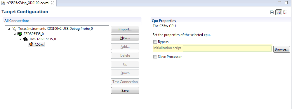
    You definitely need to initialize the chip with your program instead of relying on the GEL file. One way to test its stand-alone initialization of your program is to run the program from CCS via the USB without loading the GEL file - just delete the path to the GEL file in the highlighted field below in the Target Configuration window. Make sure it runs as expected, at the expected SYSCLK frequency.

    In your initialization, make sure you configure the PLL, reset the peripherals, disable and clear interrupts, set interrupt vectors, open clock gates, and un-idle the DMA M-port (refer to the GEL file).

    For more details on interrupt pointers, refer E2E posts and to 2.8.1 Interrupt Vector Pointers (IVPD, IVPH) of the C55x v3.x CPU Reference Guide - http://www.ti.com/lit/ug/swpu073e/swpu073e.pdf

    Hope this helps,
    Mark

  • Mark,

    You're right, my problem was the MPORTI bit of the Idle Configuration Register (ICR). I had to activate it in my initialisation. I did it after the idle state but I forgot to do it on start.

    Thank you for your information.
    Best Regards.