Other Parts Discussed in Thread: TPS65217
Hi,
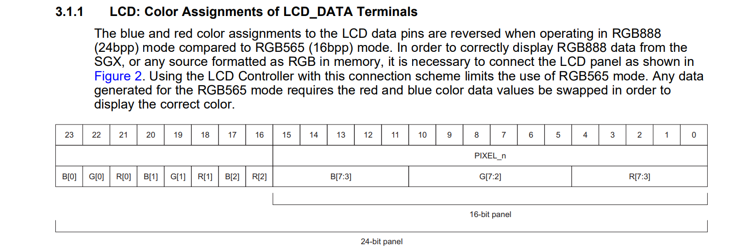
We are interfacing 7' inch 24-bit LCD display, The panel comes up and sensing touch screen properly but it is not showing 24-bit color. We have updated device tree files, please find the attached dts files below.
Kindly suggest what wrong.
am335x-boneblack-dts:
/*
* Copyright (C) 2012 Texas Instruments Incorporated - http://www.ti.com/
*
* This program is free software; you can redistribute it and/or modify
* it under the terms of the GNU General Public License version 2 as
* published by the Free Software Foundation.
*/
/dts-v1/;
#include "am33xx.dtsi"
#include <dt-bindings/pwm/pwm.h>
#include "am335x-bone-common.dtsi"
#include "am335x-boneblack-common.dtsi"
&sgx {
status = "okay";
};
/ {
model = "TI AM335x BeagleBone Black";
compatible = "ti,am335x-bone-black", "ti,am335x-bone", "ti,am33xx";
lcd_bl: backlight {
compatible = "pwm-backlight";
pwms = <&ecap0 0 50000 PWM_POLARITY_INVERTED>;
brightness-levels = <0 58 61 66 75 90 125 170 255>;
default-brightness-level = <8>;
};
panel {
compatible = "ti,tilcdc,panel";
pinctrl-names = "default", "sleep";
pinctrl-0 = <&lcd_pins_default>;
backlight = <&lcd_bl>;
status = "okay";
panel-info {
ac-bias = <255>;
ac-bias-intrpt = <0>;
dma-burst-sz = <16>;
bpp = <24>;
fdd = <0x80>;
sync-edge = <0>;
sync-ctrl = <1>;
raster-order = <0>;
fifo-th = <0>;
};
display-timings {
800x480 {
hactive = <800>;
vactive = <480>;
hback-porch = <88>;
hfront-porch = <40>;
hsync-len = <48>;
vback-porch = <32>;
vfront-porch = <13>;
vsync-len = <3>;
clock-frequency = <30000000>;
hsync-active = <0>;
vsync-active = <0>;
};
};
};
};
&cpu0_opp_table {
/*
* All PG 2.0 silicon may not support 1GHz but some of the early
* BeagleBone Blacks have PG 2.0 silicon which is guaranteed
* to support 1GHz OPP so enable it for PG 2.0 on this board.
*/
oppnitro-1000000000 {
opp-supported-hw = <0x06 0x0100>;
};
};
&lcdc {
status = "okay";
blue-and-red-wiring = "crossed";
};
am335x-bone-common.dtsi:
/*
* Copyright (C) 2012 Texas Instruments Incorporated - http://www.ti.com/
*
* This program is free software; you can redistribute it and/or modify
* it under the terms of the GNU General Public License version 2 as
* published by the Free Software Foundation.
*/
#include <dt-bindings/interrupt-controller/irq.h>
/ {
cpus {
cpu@0 {
cpu0-supply = <&dcdc2_reg>;
};
};
memory@80000000 {
device_type = "memory";
reg = <0x80000000 0x10000000>; /* 256 MB */
};
chosen {
stdout-path = &uart0;
};
leds {
pinctrl-names = "default";
pinctrl-0 = <&user_leds_s0>;
compatible = "gpio-leds";
led2 {
label = "beaglebone:green:heartbeat";
gpios = <&gpio1 21 GPIO_ACTIVE_HIGH>;
linux,default-trigger = "heartbeat";
default-state = "off";
};
led3 {
label = "beaglebone:green:mmc0";
gpios = <&gpio1 22 GPIO_ACTIVE_HIGH>;
linux,default-trigger = "mmc0";
default-state = "off";
};
led4 {
label = "beaglebone:green:usr2";
gpios = <&gpio1 23 GPIO_ACTIVE_HIGH>;
linux,default-trigger = "cpu0";
default-state = "off";
};
led5 {
label = "beaglebone:green:usr3";
gpios = <&gpio1 24 GPIO_ACTIVE_HIGH>;
linux,default-trigger = "mmc1";
default-state = "off";
};
7Inch_GPIO1 {
gpios = <&gpio1 16 GPIO_ACTIVE_HIGH>;
default-state = "on";
};
7Inch_GPIO2 {
gpios = <&gpio1 17 GPIO_ACTIVE_HIGH>;
default-state = "on";
};
7Inch_GPIO3 {
gpios = <&gpio1 28 GPIO_ACTIVE_HIGH>;
default-state = "on";
};
};
vmmcsd_fixed: fixedregulator0 {
compatible = "regulator-fixed";
regulator-name = "vmmcsd_fixed";
regulator-min-microvolt = <3300000>;
regulator-max-microvolt = <3300000>;
};
};
&am33xx_pinmux {
pinctrl-names = "default";
pinctrl-0 = <&clkout2_pin>;
user_leds_s0: user_leds_s0 {
pinctrl-single,pins = <
AM33XX_IOPAD(0x854, PIN_OUTPUT_PULLDOWN | MUX_MODE7) /* gpmc_a5.gpio1_21 */
AM33XX_IOPAD(0x858, PIN_OUTPUT_PULLUP | MUX_MODE7) /* gpmc_a6.gpio1_22 */
AM33XX_IOPAD(0x85c, PIN_OUTPUT_PULLDOWN | MUX_MODE7) /* gpmc_a7.gpio1_23 */
AM33XX_IOPAD(0x860, PIN_OUTPUT_PULLUP | MUX_MODE7) /* gpmc_a8.gpio1_24 */
AM33XX_IOPAD(0x840, PIN_OUTPUT_PULLUP | MUX_MODE7) /* gpmc_a0.gpio1_16 */
AM33XX_IOPAD(0x844, PIN_OUTPUT_PULLUP | MUX_MODE7) /* gpmc_a1.gpio1_17 */
AM33XX_IOPAD(0x878, PIN_OUTPUT_PULLUP | MUX_MODE7) /* gpmc_ben1.gpio1_28 */
>;
};
//7inch_ts_pins: 7inch_ts_pins {
//pinctrl-single,pins = <
// AM33XX_IOPAD(0x878, PIN_OUTPUT_PULLUP | MUX_MODE7) /* gpmc_ben1.gpio1_28 */
//>;
//};
i2c1_pins: pinmux_i2c1_pins {
pinctrl-single,pins = <
AM33XX_IOPAD(0x958, PIN_INPUT_PULLUP | MUX_MODE2) /* spi0_d1.i2c0_sda */
AM33XX_IOPAD(0x95c, PIN_INPUT_PULLUP | MUX_MODE2) /* spi0_cs0.i2c1_scl */
>;
};
i2c0_pins: pinmux_i2c0_pins {
pinctrl-single,pins = <
AM33XX_IOPAD(0x988, PIN_INPUT_PULLUP | MUX_MODE0) /* i2c0_sda.i2c0_sda */
AM33XX_IOPAD(0x98c, PIN_INPUT_PULLUP | MUX_MODE0) /* i2c0_scl.i2c0_scl */
>;
};
i2c2_pins: pinmux_i2c2_pins {
pinctrl-single,pins = <
AM33XX_IOPAD(0x978, PIN_INPUT_PULLUP | MUX_MODE3) /* uart1_ctsn.i2c2_sda */
AM33XX_IOPAD(0x97c, PIN_INPUT_PULLUP | MUX_MODE3) /* uart1_rtsn.i2c2_scl */
>;
};
uart2_pins: pinmux_uart2_pins {
pinctrl-single,pins = <
AM33XX_IOPAD(0x850, PIN_INPUT_PULLUP | MUX_MODE1) /* spi0_sclk.uart2_rxd */
AM33XX_IOPAD(0x854, PIN_OUTPUT_PULLDOWN | MUX_MODE1) /* spi0_d0.uart2_txd */
>;
};
uart0_pins: pinmux_uart0_pins {
pinctrl-single,pins = <
AM33XX_IOPAD(0x970, PIN_INPUT_PULLUP | MUX_MODE0) /* uart0_rxd.uart0_rxd */
AM33XX_IOPAD(0x974, PIN_OUTPUT_PULLDOWN | MUX_MODE0) /* uart0_txd.uart0_txd */
>;
};
clkout2_pin: pinmux_clkout2_pin {
pinctrl-single,pins = <
AM33XX_IOPAD(0x9b4, PIN_OUTPUT_PULLDOWN | MUX_MODE3) /* xdma_event_intr1.clkout2 */
>;
};
lcd_pins_default: lcd_pins_default {
pinctrl-single,pins = <
AM33XX_IOPAD(0x820, PIN_OUTPUT | MUX_MODE1) /* gpmc_ad8.lcd_data23 */
AM33XX_IOPAD(0x824, PIN_OUTPUT | MUX_MODE1) /* gpmc_ad9.lcd_data22 */
AM33XX_IOPAD(0x828, PIN_OUTPUT | MUX_MODE1) /* gpmc_ad10.lcd_data21 */
AM33XX_IOPAD(0x82c, PIN_OUTPUT | MUX_MODE1) /* gpmc_ad11.lcd_data20 */
AM33XX_IOPAD(0x830, PIN_OUTPUT | MUX_MODE1) /* gpmc_ad12.lcd_data19 */
AM33XX_IOPAD(0x834, PIN_OUTPUT | MUX_MODE1) /* gpmc_ad13.lcd_data18 */
AM33XX_IOPAD(0x838, PIN_OUTPUT | MUX_MODE1) /* gpmc_ad14.lcd_data17 */
AM33XX_IOPAD(0x83c, PIN_OUTPUT | MUX_MODE1) /* gpmc_ad15.lcd_data16 */
AM33XX_IOPAD(0x8a0, PIN_OUTPUT | MUX_MODE0) /* lcd_data0.lcd_data0 */
AM33XX_IOPAD(0x8a4, PIN_OUTPUT | MUX_MODE0) /* lcd_data1.lcd_data1 */
AM33XX_IOPAD(0x8a8, PIN_OUTPUT | MUX_MODE0) /* lcd_data2.lcd_data2 */
AM33XX_IOPAD(0x8ac, PIN_OUTPUT | MUX_MODE0) /* lcd_data3.lcd_data3 */
AM33XX_IOPAD(0x8b0, PIN_OUTPUT | MUX_MODE0) /* lcd_data4.lcd_data4 */
AM33XX_IOPAD(0x8b4, PIN_OUTPUT | MUX_MODE0) /* lcd_data5.lcd_data5 */
AM33XX_IOPAD(0x8b8, PIN_OUTPUT | MUX_MODE0) /* lcd_data6.lcd_data6 */
AM33XX_IOPAD(0x8bc, PIN_OUTPUT | MUX_MODE0) /* lcd_data7.lcd_data7 */
AM33XX_IOPAD(0x8c0, PIN_OUTPUT | MUX_MODE0) /* lcd_data8.lcd_data8 */
AM33XX_IOPAD(0x8c4, PIN_OUTPUT | MUX_MODE0) /* lcd_data9.lcd_data9 */
AM33XX_IOPAD(0x8c8, PIN_OUTPUT | MUX_MODE0) /* lcd_data10.lcd_data10 */
AM33XX_IOPAD(0x8cc, PIN_OUTPUT | MUX_MODE0) /* lcd_data11.lcd_data11 */
AM33XX_IOPAD(0x8d0, PIN_OUTPUT | MUX_MODE0) /* lcd_data12.lcd_data12 */
AM33XX_IOPAD(0x8d4, PIN_OUTPUT | MUX_MODE0) /* lcd_data13.lcd_data13 */
AM33XX_IOPAD(0x8d8, PIN_OUTPUT | MUX_MODE0) /* lcd_data14.lcd_data14 */
AM33XX_IOPAD(0x8dc, PIN_OUTPUT | MUX_MODE0) /* lcd_data15.lcd_data15 */
AM33XX_IOPAD(0x8e0, PIN_OUTPUT | MUX_MODE0) /* lcd_vsync.lcd_vsync */
AM33XX_IOPAD(0x8e4, PIN_OUTPUT | MUX_MODE0) /* lcd_hsync.lcd_hsync */
AM33XX_IOPAD(0x8e8, PIN_OUTPUT | MUX_MODE0) /* lcd_pclk.lcd_pclk */
AM33XX_IOPAD(0x8ec, PIN_OUTPUT | MUX_MODE0) /* lcd_ac_bias_en.lcd_ac_bias_en */
>;
};
ecap0_pins: backlight_pins {
pinctrl-single,pins = <
AM33XX_IOPAD(0x964, MUX_MODE0) /* ecap0_in_pwm0_out */
>;
};
mcasp0_pins: mcasp0_pins {
pinctrl-single,pins = <
AM33XX_IOPAD(0x9ac, PIN_INPUT_PULLUP | MUX_MODE0) /* mcasp0_ahcklx.mcasp0_ahclkx */
AM33XX_IOPAD(0x99c, PIN_OUTPUT_PULLDOWN | MUX_MODE2) /* mcasp0_ahclkr.mcasp0_axr2*/
AM33XX_IOPAD(0x994, PIN_OUTPUT_PULLUP | MUX_MODE0) /* mcasp0_fsx.mcasp0_fsx */
AM33XX_IOPAD(0x990, PIN_OUTPUT_PULLDOWN | MUX_MODE0) /* mcasp0_aclkx.mcasp0_aclkx */
AM33XX_IOPAD(0x86c, PIN_OUTPUT_PULLDOWN | MUX_MODE7) /* gpmc_a11.GPIO1_27 */
>;
};
cpsw_default: cpsw_default {
pinctrl-single,pins = <
/* Slave 1 */
AM33XX_IOPAD(0x910, PIN_INPUT_PULLUP | MUX_MODE0) /* mii1_rxerr.mii1_rxerr */
AM33XX_IOPAD(0x914, PIN_OUTPUT_PULLDOWN | MUX_MODE0) /* mii1_txen.mii1_txen */
AM33XX_IOPAD(0x918, PIN_INPUT_PULLUP | MUX_MODE0) /* mii1_rxdv.mii1_rxdv */
AM33XX_IOPAD(0x91c, PIN_OUTPUT_PULLDOWN | MUX_MODE0) /* mii1_txd3.mii1_txd3 */
AM33XX_IOPAD(0x920, PIN_OUTPUT_PULLDOWN | MUX_MODE0) /* mii1_txd2.mii1_txd2 */
AM33XX_IOPAD(0x924, PIN_OUTPUT_PULLDOWN | MUX_MODE0) /* mii1_txd1.mii1_txd1 */
AM33XX_IOPAD(0x928, PIN_OUTPUT_PULLDOWN | MUX_MODE0) /* mii1_txd0.mii1_txd0 */
AM33XX_IOPAD(0x92c, PIN_INPUT_PULLUP | MUX_MODE0) /* mii1_txclk.mii1_txclk */
AM33XX_IOPAD(0x930, PIN_INPUT_PULLUP | MUX_MODE0) /* mii1_rxclk.mii1_rxclk */
AM33XX_IOPAD(0x934, PIN_INPUT_PULLUP | MUX_MODE0) /* mii1_rxd3.mii1_rxd3 */
AM33XX_IOPAD(0x938, PIN_INPUT_PULLUP | MUX_MODE0) /* mii1_rxd2.mii1_rxd2 */
AM33XX_IOPAD(0x93c, PIN_INPUT_PULLUP | MUX_MODE0) /* mii1_rxd1.mii1_rxd1 */
AM33XX_IOPAD(0x940, PIN_INPUT_PULLUP | MUX_MODE0) /* mii1_rxd0.mii1_rxd0 */
>;
};
cpsw_sleep: cpsw_sleep {
pinctrl-single,pins = <
/* Slave 1 reset value */
AM33XX_IOPAD(0x910, PIN_INPUT_PULLDOWN | MUX_MODE7)
AM33XX_IOPAD(0x914, PIN_INPUT_PULLDOWN | MUX_MODE7)
AM33XX_IOPAD(0x918, PIN_INPUT_PULLDOWN | MUX_MODE7)
AM33XX_IOPAD(0x91c, PIN_INPUT_PULLDOWN | MUX_MODE7)
AM33XX_IOPAD(0x920, PIN_INPUT_PULLDOWN | MUX_MODE7)
AM33XX_IOPAD(0x924, PIN_INPUT_PULLDOWN | MUX_MODE7)
AM33XX_IOPAD(0x928, PIN_INPUT_PULLDOWN | MUX_MODE7)
AM33XX_IOPAD(0x92c, PIN_INPUT_PULLDOWN | MUX_MODE7)
AM33XX_IOPAD(0x930, PIN_INPUT_PULLDOWN | MUX_MODE7)
AM33XX_IOPAD(0x934, PIN_INPUT_PULLDOWN | MUX_MODE7)
AM33XX_IOPAD(0x938, PIN_INPUT_PULLDOWN | MUX_MODE7)
AM33XX_IOPAD(0x93c, PIN_INPUT_PULLDOWN | MUX_MODE7)
AM33XX_IOPAD(0x940, PIN_INPUT_PULLDOWN | MUX_MODE7)
>;
};
davinci_mdio_default: davinci_mdio_default {
pinctrl-single,pins = <
/* MDIO */
AM33XX_IOPAD(0x948, PIN_INPUT_PULLUP | SLEWCTRL_FAST | MUX_MODE0) /* mdio_data.mdio_data */
AM33XX_IOPAD(0x94c, PIN_OUTPUT_PULLUP | MUX_MODE0) /* mdio_clk.mdio_clk */
>;
};
davinci_mdio_sleep: davinci_mdio_sleep {
pinctrl-single,pins = <
/* MDIO reset value */
AM33XX_IOPAD(0x948, PIN_INPUT_PULLDOWN | MUX_MODE7)
AM33XX_IOPAD(0x94c, PIN_INPUT_PULLDOWN | MUX_MODE7)
>;
};
mmc1_pins: pinmux_mmc1_pins {
pinctrl-single,pins = <
AM33XX_IOPAD(0x960, PIN_INPUT | MUX_MODE7) /* spio0_cs1.gpio0_6 */
AM33XX_IOPAD(0x8fc, PIN_INPUT_PULLUP | MUX_MODE0) /* mmc0_dat0.mmc0_dat0 */
AM33XX_IOPAD(0x8f8, PIN_INPUT_PULLUP | MUX_MODE0) /* mmc0_dat1.mmc0_dat1 */
AM33XX_IOPAD(0x8f4, PIN_INPUT_PULLUP | MUX_MODE0) /* mmc0_dat2.mmc0_dat2 */
AM33XX_IOPAD(0x8f0, PIN_INPUT_PULLUP | MUX_MODE0) /* mmc0_dat3.mmc0_dat3 */
AM33XX_IOPAD(0x904, PIN_INPUT_PULLUP | MUX_MODE0) /* mmc0_cmd.mmc0_cmd */
AM33XX_IOPAD(0x900, PIN_INPUT_PULLUP | MUX_MODE0) /* mmc0_clk.mmc0_clk */
AM33XX_IOPAD(0x9a0, PIN_INPUT | MUX_MODE4) /* mcasp0_aclkr.mmc0_sdwp */
>;
};
emmc_pins: pinmux_emmc_pins {
pinctrl-single,pins = <
AM33XX_IOPAD(0x880, PIN_INPUT_PULLUP | MUX_MODE2) /* gpmc_csn1.mmc1_clk */
AM33XX_IOPAD(0x884, PIN_INPUT_PULLUP | MUX_MODE2) /* gpmc_csn2.mmc1_cmd */
AM33XX_IOPAD(0x800, PIN_INPUT_PULLUP | MUX_MODE1) /* gpmc_ad0.mmc1_dat0 */
AM33XX_IOPAD(0x804, PIN_INPUT_PULLUP | MUX_MODE1) /* gpmc_ad1.mmc1_dat1 */
AM33XX_IOPAD(0x808, PIN_INPUT_PULLUP | MUX_MODE1) /* gpmc_ad2.mmc1_dat2 */
AM33XX_IOPAD(0x80c, PIN_INPUT_PULLUP | MUX_MODE1) /* gpmc_ad3.mmc1_dat3 */
AM33XX_IOPAD(0x810, PIN_INPUT_PULLUP | MUX_MODE1) /* gpmc_ad4.mmc1_dat4 */
AM33XX_IOPAD(0x814, PIN_INPUT_PULLUP | MUX_MODE1) /* gpmc_ad5.mmc1_dat5 */
AM33XX_IOPAD(0x818, PIN_INPUT_PULLUP | MUX_MODE1) /* gpmc_ad6.mmc1_dat6 */
AM33XX_IOPAD(0x81c, PIN_INPUT_PULLUP | MUX_MODE1) /* gpmc_ad7.mmc1_dat7 */
>;
};
};
&uart0 {
pinctrl-names = "default";
pinctrl-0 = <&uart0_pins>;
status = "okay";
};
&uart2 {
pinctrl-names = "default";
pinctrl-0 = <&uart2_pins>;
status = "okay";
};
&usb {
status = "okay";
};
&i2c1 {
pinctrl-names = "default";
pinctrl-0 = <&i2c1_pins>;
status = "okay";
clock-frequency = <400000>;
edt-ft5x06@38 {
compatible = "edt-ft5x06";
reg = <0x38>;
attb-gpio = <&gpio1 28 GPIO_ACTIVE_HIGH>;
pinctrl-names = "default";
// pinctrl-0 = <&edt-ft5x06_pins>;
interrupt-parent = <&gpio1>;
interrupts = <28 IRQ_TYPE_LEVEL_LOW>; /* gpio 31 */
interrupts-extended = <&gpio1 28 IRQ_TYPE_EDGE_FALLING>;
// <&am33xx_pinmux 0x878>;
interrupt-names = "tsc", "wakeup";
//wakeup-gpios = <&gpio1 28 GPIO_ACTIVE_LOW>;
touchscreen-size-x = <800>;
touchscreen-size-y = <480>;
wakeup-source;
};
};
&usb_ctrl_mod {
status = "okay";
};
&usb0_phy {
status = "okay";
};
&usb1_phy {
status = "okay";
};
&usb0 {
status = "okay";
dr_mode = "peripheral";
interrupts-extended = <&intc 18 &tps 0>;
interrupt-names = "mc", "vbus";
};
&usb1 {
status = "okay";
dr_mode = "host";
};
&cppi41dma {
status = "okay";
};
&i2c0 {
pinctrl-names = "default";
pinctrl-0 = <&i2c0_pins>;
status = "okay";
clock-frequency = <400000>;
tps: tps@24 {
reg = <0x24>;
};
baseboard_eeprom: baseboard_eeprom@50 {
compatible = "atmel,24c256";
reg = <0x50>;
#address-cells = <1>;
#size-cells = <1>;
baseboard_data: baseboard_data@0 {
reg = <0 0x100>;
};
};
};
&i2c2 {
pinctrl-names = "default";
pinctrl-0 = <&i2c2_pins>;
status = "okay";
clock-frequency = <100000>;
cape_eeprom0: cape_eeprom0@54 {
compatible = "atmel,24c256";
reg = <0x54>;
#address-cells = <1>;
#size-cells = <1>;
cape0_data: cape_data@0 {
reg = <0 0x100>;
};
};
cape_eeprom1: cape_eeprom1@55 {
compatible = "atmel,24c256";
reg = <0x55>;
#address-cells = <1>;
#size-cells = <1>;
cape1_data: cape_data@0 {
reg = <0 0x100>;
};
};
cape_eeprom2: cape_eeprom2@56 {
compatible = "atmel,24c256";
reg = <0x56>;
#address-cells = <1>;
#size-cells = <1>;
cape2_data: cape_data@0 {
reg = <0 0x100>;
};
};
cape_eeprom3: cape_eeprom3@57 {
compatible = "atmel,24c256";
reg = <0x57>;
#address-cells = <1>;
#size-cells = <1>;
cape3_data: cape_data@0 {
reg = <0 0x100>;
};
};
};
&epwmss0 {
status = "okay";
ecap0: ecap@48300100 {
status = "okay";
pinctrl-names = "default";
pinctrl-0 = <&ecap0_pins>;
};
};
/include/ "tps65217.dtsi"
&tps {
/*
* Configure pmic to enter OFF-state instead of SLEEP-state ("RTC-only
* mode") at poweroff. Most BeagleBone versions do not support RTC-only
* mode and risk hardware damage if this mode is entered.
*
* For details, see linux-omap mailing list May 2015 thread
* [PATCH] ARM: dts: am335x-bone* enable pmic-shutdown-controller
* In particular, messages:
* www.spinics.net/.../msg118585.html
* www.spinics.net/.../msg118615.html
*
* You can override this later with
* &tps { /delete-property/ ti,pmic-shutdown-controller; }
* if you want to use RTC-only mode and made sure you are not affected
* by the hardware problems. (Tip: double-check by performing a current
* measurement after shutdown: it should be less than 1 mA.)
*/
interrupts = <7>; /* NMI */
interrupt-parent = <&intc>;
ti,pmic-shutdown-controller;
charger {
status = "okay";
};
pwrbutton {
status = "okay";
};
regulators {
dcdc1_reg: regulator@0 {
regulator-name = "vdds_dpr";
regulator-always-on;
};
dcdc2_reg: regulator@1 {
/* VDD_MPU voltage limits 0.95V - 1.26V with +/-4% tolerance */
regulator-name = "vdd_mpu";
regulator-min-microvolt = <925000>;
regulator-max-microvolt = <1351500>;
regulator-boot-on;
regulator-always-on;
};
dcdc3_reg: regulator@2 {
/* VDD_CORE voltage limits 0.95V - 1.1V with +/-4% tolerance */
regulator-name = "vdd_core";
regulator-min-microvolt = <925000>;
regulator-max-microvolt = <1150000>;
regulator-boot-on;
regulator-always-on;
};
ldo1_reg: regulator@3 {
regulator-name = "vio,vrtc,vdds";
regulator-always-on;
};
ldo2_reg: regulator@4 {
regulator-name = "vdd_3v3aux";
regulator-always-on;
};
ldo3_reg: regulator@5 {
regulator-name = "vdd_1v8";
regulator-always-on;
};
ldo4_reg: regulator@6 {
regulator-name = "vdd_3v3a";
regulator-always-on;
};
};
};
&cpsw_emac0 {
phy_id = <&davinci_mdio>, <0>;
phy-mode = "mii";
};
&mac {
slaves = <1>;
pinctrl-names = "default", "sleep";
pinctrl-0 = <&cpsw_default>;
pinctrl-1 = <&cpsw_sleep>;
status = "okay";
};
&davinci_mdio {
pinctrl-names = "default", "sleep";
pinctrl-0 = <&davinci_mdio_default>;
pinctrl-1 = <&davinci_mdio_sleep>;
status = "okay";
};
&mmc1 {
status = "okay";
bus-width = <0x4>;
pinctrl-names = "default";
pinctrl-0 = <&mmc1_pins>;
cd-gpios = <&gpio0 6 GPIO_ACTIVE_LOW>;
};
&aes {
status = "okay";
};
&sham {
status = "okay";
};
&rtc {
clocks = <&clk_32768_ck>, <&clkdiv32k_ick>;
clock-names = "ext-clk", "int-clk";
system-power-controller;
};
&wkup_m3_ipc {
ti,scale-data-fw = "am335x-bone-scale-data.bin";
};
&pruss_soc_bus {
status = "okay";
pruss: pruss@0 {
status = "okay";
};
};
Thanks
/*
* Copyright (C) 2012 Texas Instruments Incorporated - http://www.ti.com/
*
* This program is free software; you can redistribute it and/or modify
* it under the terms of the GNU General Public License version 2 as
* published by the Free Software Foundation.
*/
#include <dt-bindings/interrupt-controller/irq.h>
/ {
cpus {
cpu@0 {
cpu0-supply = <&dcdc2_reg>;
};
};
memory@80000000 {
device_type = "memory";
reg = <0x80000000 0x10000000>; /* 256 MB */
};
chosen {
stdout-path = &uart0;
};
leds {
pinctrl-names = "default";
pinctrl-0 = <&user_leds_s0>;
compatible = "gpio-leds";
led2 {
label = "beaglebone:green:heartbeat";
gpios = <&gpio1 21 GPIO_ACTIVE_HIGH>;
linux,default-trigger = "heartbeat";
default-state = "off";
};
led3 {
label = "beaglebone:green:mmc0";
gpios = <&gpio1 22 GPIO_ACTIVE_HIGH>;
linux,default-trigger = "mmc0";
default-state = "off";
};
led4 {
label = "beaglebone:green:usr2";
gpios = <&gpio1 23 GPIO_ACTIVE_HIGH>;
linux,default-trigger = "cpu0";
default-state = "off";
};
led5 {
label = "beaglebone:green:usr3";
gpios = <&gpio1 24 GPIO_ACTIVE_HIGH>;
linux,default-trigger = "mmc1";
default-state = "off";
};
7Inch_GPIO1 {
gpios = <&gpio1 16 GPIO_ACTIVE_HIGH>;
default-state = "on";
};
7Inch_GPIO2 {
gpios = <&gpio1 17 GPIO_ACTIVE_HIGH>;
default-state = "on";
};
7Inch_GPIO3 {
gpios = <&gpio1 28 GPIO_ACTIVE_HIGH>;
default-state = "on";
};
};
vmmcsd_fixed: fixedregulator0 {
compatible = "regulator-fixed";
regulator-name = "vmmcsd_fixed";
regulator-min-microvolt = <3300000>;
regulator-max-microvolt = <3300000>;
};
};
&am33xx_pinmux {
pinctrl-names = "default";
pinctrl-0 = <&clkout2_pin>;
user_leds_s0: user_leds_s0 {
pinctrl-single,pins = <
AM33XX_IOPAD(0x854, PIN_OUTPUT_PULLDOWN | MUX_MODE7) /* gpmc_a5.gpio1_21 */
AM33XX_IOPAD(0x858, PIN_OUTPUT_PULLUP | MUX_MODE7) /* gpmc_a6.gpio1_22 */
AM33XX_IOPAD(0x85c, PIN_OUTPUT_PULLDOWN | MUX_MODE7) /* gpmc_a7.gpio1_23 */
AM33XX_IOPAD(0x860, PIN_OUTPUT_PULLUP | MUX_MODE7) /* gpmc_a8.gpio1_24 */
AM33XX_IOPAD(0x840, PIN_OUTPUT_PULLUP | MUX_MODE7) /* gpmc_a0.gpio1_16 */
AM33XX_IOPAD(0x844, PIN_OUTPUT_PULLUP | MUX_MODE7) /* gpmc_a1.gpio1_17 */
AM33XX_IOPAD(0x878, PIN_OUTPUT_PULLUP | MUX_MODE7) /* gpmc_ben1.gpio1_28 */
>;
};
//7inch_ts_pins: 7inch_ts_pins {
//pinctrl-single,pins = <
// AM33XX_IOPAD(0x878, PIN_OUTPUT_PULLUP | MUX_MODE7) /* gpmc_ben1.gpio1_28 */
//>;
//};
i2c1_pins: pinmux_i2c1_pins {
pinctrl-single,pins = <
AM33XX_IOPAD(0x958, PIN_INPUT_PULLUP | MUX_MODE2) /* spi0_d1.i2c0_sda */
AM33XX_IOPAD(0x95c, PIN_INPUT_PULLUP | MUX_MODE2) /* spi0_cs0.i2c1_scl */
>;
};
i2c0_pins: pinmux_i2c0_pins {
pinctrl-single,pins = <
AM33XX_IOPAD(0x988, PIN_INPUT_PULLUP | MUX_MODE0) /* i2c0_sda.i2c0_sda */
AM33XX_IOPAD(0x98c, PIN_INPUT_PULLUP | MUX_MODE0) /* i2c0_scl.i2c0_scl */
>;
};
i2c2_pins: pinmux_i2c2_pins {
pinctrl-single,pins = <
AM33XX_IOPAD(0x978, PIN_INPUT_PULLUP | MUX_MODE3) /* uart1_ctsn.i2c2_sda */
AM33XX_IOPAD(0x97c, PIN_INPUT_PULLUP | MUX_MODE3) /* uart1_rtsn.i2c2_scl */
>;
};
uart2_pins: pinmux_uart2_pins {
pinctrl-single,pins = <
AM33XX_IOPAD(0x850, PIN_INPUT_PULLUP | MUX_MODE1) /* spi0_sclk.uart2_rxd */
AM33XX_IOPAD(0x854, PIN_OUTPUT_PULLDOWN | MUX_MODE1) /* spi0_d0.uart2_txd */
>;
};
uart0_pins: pinmux_uart0_pins {
pinctrl-single,pins = <
AM33XX_IOPAD(0x970, PIN_INPUT_PULLUP | MUX_MODE0) /* uart0_rxd.uart0_rxd */
AM33XX_IOPAD(0x974, PIN_OUTPUT_PULLDOWN | MUX_MODE0) /* uart0_txd.uart0_txd */
>;
};
clkout2_pin: pinmux_clkout2_pin {
pinctrl-single,pins = <
AM33XX_IOPAD(0x9b4, PIN_OUTPUT_PULLDOWN | MUX_MODE3) /* xdma_event_intr1.clkout2 */
>;
};
lcd_pins_default: lcd_pins_default {
pinctrl-single,pins = <
AM33XX_IOPAD(0x820, PIN_OUTPUT | MUX_MODE1) /* gpmc_ad8.lcd_data23 */
AM33XX_IOPAD(0x824, PIN_OUTPUT | MUX_MODE1) /* gpmc_ad9.lcd_data22 */
AM33XX_IOPAD(0x828, PIN_OUTPUT | MUX_MODE1) /* gpmc_ad10.lcd_data21 */
AM33XX_IOPAD(0x82c, PIN_OUTPUT | MUX_MODE1) /* gpmc_ad11.lcd_data20 */
AM33XX_IOPAD(0x830, PIN_OUTPUT | MUX_MODE1) /* gpmc_ad12.lcd_data19 */
AM33XX_IOPAD(0x834, PIN_OUTPUT | MUX_MODE1) /* gpmc_ad13.lcd_data18 */
AM33XX_IOPAD(0x838, PIN_OUTPUT | MUX_MODE1) /* gpmc_ad14.lcd_data17 */
AM33XX_IOPAD(0x83c, PIN_OUTPUT | MUX_MODE1) /* gpmc_ad15.lcd_data16 */
AM33XX_IOPAD(0x8a0, PIN_OUTPUT | MUX_MODE0) /* lcd_data0.lcd_data0 */
AM33XX_IOPAD(0x8a4, PIN_OUTPUT | MUX_MODE0) /* lcd_data1.lcd_data1 */
AM33XX_IOPAD(0x8a8, PIN_OUTPUT | MUX_MODE0) /* lcd_data2.lcd_data2 */
AM33XX_IOPAD(0x8ac, PIN_OUTPUT | MUX_MODE0) /* lcd_data3.lcd_data3 */
AM33XX_IOPAD(0x8b0, PIN_OUTPUT | MUX_MODE0) /* lcd_data4.lcd_data4 */
AM33XX_IOPAD(0x8b4, PIN_OUTPUT | MUX_MODE0) /* lcd_data5.lcd_data5 */
AM33XX_IOPAD(0x8b8, PIN_OUTPUT | MUX_MODE0) /* lcd_data6.lcd_data6 */
AM33XX_IOPAD(0x8bc, PIN_OUTPUT | MUX_MODE0) /* lcd_data7.lcd_data7 */
AM33XX_IOPAD(0x8c0, PIN_OUTPUT | MUX_MODE0) /* lcd_data8.lcd_data8 */
AM33XX_IOPAD(0x8c4, PIN_OUTPUT | MUX_MODE0) /* lcd_data9.lcd_data9 */
AM33XX_IOPAD(0x8c8, PIN_OUTPUT | MUX_MODE0) /* lcd_data10.lcd_data10 */
AM33XX_IOPAD(0x8cc, PIN_OUTPUT | MUX_MODE0) /* lcd_data11.lcd_data11 */
AM33XX_IOPAD(0x8d0, PIN_OUTPUT | MUX_MODE0) /* lcd_data12.lcd_data12 */
AM33XX_IOPAD(0x8d4, PIN_OUTPUT | MUX_MODE0) /* lcd_data13.lcd_data13 */
AM33XX_IOPAD(0x8d8, PIN_OUTPUT | MUX_MODE0) /* lcd_data14.lcd_data14 */
AM33XX_IOPAD(0x8dc, PIN_OUTPUT | MUX_MODE0) /* lcd_data15.lcd_data15 */
AM33XX_IOPAD(0x8e0, PIN_OUTPUT | MUX_MODE0) /* lcd_vsync.lcd_vsync */
AM33XX_IOPAD(0x8e4, PIN_OUTPUT | MUX_MODE0) /* lcd_hsync.lcd_hsync */
AM33XX_IOPAD(0x8e8, PIN_OUTPUT | MUX_MODE0) /* lcd_pclk.lcd_pclk */
AM33XX_IOPAD(0x8ec, PIN_OUTPUT | MUX_MODE0) /* lcd_ac_bias_en.lcd_ac_bias_en */
>;
};
ecap0_pins: backlight_pins {
pinctrl-single,pins = <
AM33XX_IOPAD(0x964, MUX_MODE0) /* ecap0_in_pwm0_out */
>;
};
mcasp0_pins: mcasp0_pins {
pinctrl-single,pins = <
AM33XX_IOPAD(0x9ac, PIN_INPUT_PULLUP | MUX_MODE0) /* mcasp0_ahcklx.mcasp0_ahclkx */
AM33XX_IOPAD(0x99c, PIN_OUTPUT_PULLDOWN | MUX_MODE2) /* mcasp0_ahclkr.mcasp0_axr2*/
AM33XX_IOPAD(0x994, PIN_OUTPUT_PULLUP | MUX_MODE0) /* mcasp0_fsx.mcasp0_fsx */
AM33XX_IOPAD(0x990, PIN_OUTPUT_PULLDOWN | MUX_MODE0) /* mcasp0_aclkx.mcasp0_aclkx */
AM33XX_IOPAD(0x86c, PIN_OUTPUT_PULLDOWN | MUX_MODE7) /* gpmc_a11.GPIO1_27 */
>;
};
cpsw_default: cpsw_default {
pinctrl-single,pins = <
/* Slave 1 */
AM33XX_IOPAD(0x910, PIN_INPUT_PULLUP | MUX_MODE0) /* mii1_rxerr.mii1_rxerr */
AM33XX_IOPAD(0x914, PIN_OUTPUT_PULLDOWN | MUX_MODE0) /* mii1_txen.mii1_txen */
AM33XX_IOPAD(0x918, PIN_INPUT_PULLUP | MUX_MODE0) /* mii1_rxdv.mii1_rxdv */
AM33XX_IOPAD(0x91c, PIN_OUTPUT_PULLDOWN | MUX_MODE0) /* mii1_txd3.mii1_txd3 */
AM33XX_IOPAD(0x920, PIN_OUTPUT_PULLDOWN | MUX_MODE0) /* mii1_txd2.mii1_txd2 */
AM33XX_IOPAD(0x924, PIN_OUTPUT_PULLDOWN | MUX_MODE0) /* mii1_txd1.mii1_txd1 */
AM33XX_IOPAD(0x928, PIN_OUTPUT_PULLDOWN | MUX_MODE0) /* mii1_txd0.mii1_txd0 */
AM33XX_IOPAD(0x92c, PIN_INPUT_PULLUP | MUX_MODE0) /* mii1_txclk.mii1_txclk */
AM33XX_IOPAD(0x930, PIN_INPUT_PULLUP | MUX_MODE0) /* mii1_rxclk.mii1_rxclk */
AM33XX_IOPAD(0x934, PIN_INPUT_PULLUP | MUX_MODE0) /* mii1_rxd3.mii1_rxd3 */
AM33XX_IOPAD(0x938, PIN_INPUT_PULLUP | MUX_MODE0) /* mii1_rxd2.mii1_rxd2 */
AM33XX_IOPAD(0x93c, PIN_INPUT_PULLUP | MUX_MODE0) /* mii1_rxd1.mii1_rxd1 */
AM33XX_IOPAD(0x940, PIN_INPUT_PULLUP | MUX_MODE0) /* mii1_rxd0.mii1_rxd0 */
>;
};
cpsw_sleep: cpsw_sleep {
pinctrl-single,pins = <
/* Slave 1 reset value */
AM33XX_IOPAD(0x910, PIN_INPUT_PULLDOWN | MUX_MODE7)
AM33XX_IOPAD(0x914, PIN_INPUT_PULLDOWN | MUX_MODE7)
AM33XX_IOPAD(0x918, PIN_INPUT_PULLDOWN | MUX_MODE7)
AM33XX_IOPAD(0x91c, PIN_INPUT_PULLDOWN | MUX_MODE7)
AM33XX_IOPAD(0x920, PIN_INPUT_PULLDOWN | MUX_MODE7)
AM33XX_IOPAD(0x924, PIN_INPUT_PULLDOWN | MUX_MODE7)
AM33XX_IOPAD(0x928, PIN_INPUT_PULLDOWN | MUX_MODE7)
AM33XX_IOPAD(0x92c, PIN_INPUT_PULLDOWN | MUX_MODE7)
AM33XX_IOPAD(0x930, PIN_INPUT_PULLDOWN | MUX_MODE7)
AM33XX_IOPAD(0x934, PIN_INPUT_PULLDOWN | MUX_MODE7)
AM33XX_IOPAD(0x938, PIN_INPUT_PULLDOWN | MUX_MODE7)
AM33XX_IOPAD(0x93c, PIN_INPUT_PULLDOWN | MUX_MODE7)
AM33XX_IOPAD(0x940, PIN_INPUT_PULLDOWN | MUX_MODE7)
>;
};
davinci_mdio_default: davinci_mdio_default {
pinctrl-single,pins = <
/* MDIO */
AM33XX_IOPAD(0x948, PIN_INPUT_PULLUP | SLEWCTRL_FAST | MUX_MODE0) /* mdio_data.mdio_data */
AM33XX_IOPAD(0x94c, PIN_OUTPUT_PULLUP | MUX_MODE0) /* mdio_clk.mdio_clk */
>;
};
davinci_mdio_sleep: davinci_mdio_sleep {
pinctrl-single,pins = <
/* MDIO reset value */
AM33XX_IOPAD(0x948, PIN_INPUT_PULLDOWN | MUX_MODE7)
AM33XX_IOPAD(0x94c, PIN_INPUT_PULLDOWN | MUX_MODE7)
>;
};
mmc1_pins: pinmux_mmc1_pins {
pinctrl-single,pins = <
AM33XX_IOPAD(0x960, PIN_INPUT | MUX_MODE7) /* spio0_cs1.gpio0_6 */
AM33XX_IOPAD(0x8fc, PIN_INPUT_PULLUP | MUX_MODE0) /* mmc0_dat0.mmc0_dat0 */
AM33XX_IOPAD(0x8f8, PIN_INPUT_PULLUP | MUX_MODE0) /* mmc0_dat1.mmc0_dat1 */
AM33XX_IOPAD(0x8f4, PIN_INPUT_PULLUP | MUX_MODE0) /* mmc0_dat2.mmc0_dat2 */
AM33XX_IOPAD(0x8f0, PIN_INPUT_PULLUP | MUX_MODE0) /* mmc0_dat3.mmc0_dat3 */
AM33XX_IOPAD(0x904, PIN_INPUT_PULLUP | MUX_MODE0) /* mmc0_cmd.mmc0_cmd */
AM33XX_IOPAD(0x900, PIN_INPUT_PULLUP | MUX_MODE0) /* mmc0_clk.mmc0_clk */
AM33XX_IOPAD(0x9a0, PIN_INPUT | MUX_MODE4) /* mcasp0_aclkr.mmc0_sdwp */
>;
};
emmc_pins: pinmux_emmc_pins {
pinctrl-single,pins = <
AM33XX_IOPAD(0x880, PIN_INPUT_PULLUP | MUX_MODE2) /* gpmc_csn1.mmc1_clk */
AM33XX_IOPAD(0x884, PIN_INPUT_PULLUP | MUX_MODE2) /* gpmc_csn2.mmc1_cmd */
AM33XX_IOPAD(0x800, PIN_INPUT_PULLUP | MUX_MODE1) /* gpmc_ad0.mmc1_dat0 */
AM33XX_IOPAD(0x804, PIN_INPUT_PULLUP | MUX_MODE1) /* gpmc_ad1.mmc1_dat1 */
AM33XX_IOPAD(0x808, PIN_INPUT_PULLUP | MUX_MODE1) /* gpmc_ad2.mmc1_dat2 */
AM33XX_IOPAD(0x80c, PIN_INPUT_PULLUP | MUX_MODE1) /* gpmc_ad3.mmc1_dat3 */
AM33XX_IOPAD(0x810, PIN_INPUT_PULLUP | MUX_MODE1) /* gpmc_ad4.mmc1_dat4 */
AM33XX_IOPAD(0x814, PIN_INPUT_PULLUP | MUX_MODE1) /* gpmc_ad5.mmc1_dat5 */
AM33XX_IOPAD(0x818, PIN_INPUT_PULLUP | MUX_MODE1) /* gpmc_ad6.mmc1_dat6 */
AM33XX_IOPAD(0x81c, PIN_INPUT_PULLUP | MUX_MODE1) /* gpmc_ad7.mmc1_dat7 */
>;
};
};
&uart0 {
pinctrl-names = "default";
pinctrl-0 = <&uart0_pins>;
status = "okay";
};
&uart2 {
pinctrl-names = "default";
pinctrl-0 = <&uart2_pins>;
status = "okay";
};
&usb {
status = "okay";
};
&i2c1 {
pinctrl-names = "default";
pinctrl-0 = <&i2c1_pins>;
status = "okay";
clock-frequency = <400000>;
edt-ft5x06@38 {
compatible = "edt-ft5x06";
reg = <0x38>;
attb-gpio = <&gpio1 28 GPIO_ACTIVE_HIGH>;
pinctrl-names = "default";
// pinctrl-0 = <&edt-ft5x06_pins>;
interrupt-parent = <&gpio1>;
interrupts = <28 IRQ_TYPE_LEVEL_LOW>; /* gpio 31 */
interrupts-extended = <&gpio1 28 IRQ_TYPE_EDGE_FALLING>;
// <&am33xx_pinmux 0x878>;
interrupt-names = "tsc", "wakeup";
//wakeup-gpios = <&gpio1 28 GPIO_ACTIVE_LOW>;
touchscreen-size-x = <800>;
touchscreen-size-y = <480>;
wakeup-source;
};
};
&usb_ctrl_mod {
status = "okay";
};
&usb0_phy {
status = "okay";
};
&usb1_phy {
status = "okay";
};
&usb0 {
status = "okay";
dr_mode = "peripheral";
interrupts-extended = <&intc 18 &tps 0>;
interrupt-names = "mc", "vbus";
};
&usb1 {
status = "okay";
dr_mode = "host";
};
&cppi41dma {
status = "okay";
};
&i2c0 {
pinctrl-names = "default";
pinctrl-0 = <&i2c0_pins>;
status = "okay";
clock-frequency = <400000>;
tps: tps@24 {
reg = <0x24>;
};
baseboard_eeprom: baseboard_eeprom@50 {
compatible = "atmel,24c256";
reg = <0x50>;
#address-cells = <1>;
#size-cells = <1>;
baseboard_data: baseboard_data@0 {
reg = <0 0x100>;
};
};
};
&i2c2 {
pinctrl-names = "default";
pinctrl-0 = <&i2c2_pins>;
status = "okay";
clock-frequency = <100000>;
cape_eeprom0: cape_eeprom0@54 {
compatible = "atmel,24c256";
reg = <0x54>;
#address-cells = <1>;
#size-cells = <1>;
cape0_data: cape_data@0 {
reg = <0 0x100>;
};
};
cape_eeprom1: cape_eeprom1@55 {
compatible = "atmel,24c256";
reg = <0x55>;
#address-cells = <1>;
#size-cells = <1>;
cape1_data: cape_data@0 {
reg = <0 0x100>;
};
};
cape_eeprom2: cape_eeprom2@56 {
compatible = "atmel,24c256";
reg = <0x56>;
#address-cells = <1>;
#size-cells = <1>;
cape2_data: cape_data@0 {
reg = <0 0x100>;
};
};
cape_eeprom3: cape_eeprom3@57 {
compatible = "atmel,24c256";
reg = <0x57>;
#address-cells = <1>;
#size-cells = <1>;
cape3_data: cape_data@0 {
reg = <0 0x100>;
};
};
};
&epwmss0 {
status = "okay";
ecap0: ecap@48300100 {
status = "okay";
pinctrl-names = "default";
pinctrl-0 = <&ecap0_pins>;
};
};
/include/ "tps65217.dtsi"
&tps {
/*
* Configure pmic to enter OFF-state instead of SLEEP-state ("RTC-only
* mode") at poweroff. Most BeagleBone versions do not support RTC-only
* mode and risk hardware damage if this mode is entered.
*
* For details, see linux-omap mailing list May 2015 thread
* [PATCH] ARM: dts: am335x-bone* enable pmic-shutdown-controller
* In particular, messages:
* www.spinics.net/.../msg118585.html
* www.spinics.net/.../msg118615.html
*
* You can override this later with
* &tps { /delete-property/ ti,pmic-shutdown-controller; }
* if you want to use RTC-only mode and made sure you are not affected
* by the hardware problems. (Tip: double-check by performing a current
* measurement after shutdown: it should be less than 1 mA.)
*/
interrupts = <7>; /* NMI */
interrupt-parent = <&intc>;
ti,pmic-shutdown-controller;
charger {
status = "okay";
};
pwrbutton {
status = "okay";
};
regulators {
dcdc1_reg: regulator@0 {
regulator-name = "vdds_dpr";
regulator-always-on;
};
dcdc2_reg: regulator@1 {
/* VDD_MPU voltage limits 0.95V - 1.26V with +/-4% tolerance */
regulator-name = "vdd_mpu";
regulator-min-microvolt = <925000>;
regulator-max-microvolt = <1351500>;
regulator-boot-on;
regulator-always-on;
};
dcdc3_reg: regulator@2 {
/* VDD_CORE voltage limits 0.95V - 1.1V with +/-4% tolerance */
regulator-name = "vdd_core";
regulator-min-microvolt = <925000>;
regulator-max-microvolt = <1150000>;
regulator-boot-on;
regulator-always-on;
};
ldo1_reg: regulator@3 {
regulator-name = "vio,vrtc,vdds";
regulator-always-on;
};
ldo2_reg: regulator@4 {
regulator-name = "vdd_3v3aux";
regulator-always-on;
};
ldo3_reg: regulator@5 {
regulator-name = "vdd_1v8";
regulator-always-on;
};
ldo4_reg: regulator@6 {
regulator-name = "vdd_3v3a";
regulator-always-on;
};
};
};
&cpsw_emac0 {
phy_id = <&davinci_mdio>, <0>;
phy-mode = "mii";
};
&mac {
slaves = <1>;
pinctrl-names = "default", "sleep";
pinctrl-0 = <&cpsw_default>;
pinctrl-1 = <&cpsw_sleep>;
status = "okay";
};
&davinci_mdio {
pinctrl-names = "default", "sleep";
pinctrl-0 = <&davinci_mdio_default>;
pinctrl-1 = <&davinci_mdio_sleep>;
status = "okay";
};
&mmc1 {
status = "okay";
bus-width = <0x4>;
pinctrl-names = "default";
pinctrl-0 = <&mmc1_pins>;
cd-gpios = <&gpio0 6 GPIO_ACTIVE_LOW>;
};
&aes {
status = "okay";
};
&sham {
status = "okay";
};
&rtc {
clocks = <&clk_32768_ck>, <&clkdiv32k_ick>;
clock-names = "ext-clk", "int-clk";
system-power-controller;
};
&wkup_m3_ipc {
ti,scale-data-fw = "am335x-bone-scale-data.bin";
};
&pruss_soc_bus {
status = "okay";
pruss: pruss@0 {
status = "okay";
};
};