This thread has been locked.

If you have a related question, please click the "Ask a related question" button in the top right corner. The newly created question will be automatically linked to this question.

RTOS/TDA2P-ABZ: Working of ADV7393 ON TDA2PX

Part Number: TDA2P-ABZ

Tool/software: TI-RTOS

Hi All,

I am working on TDA2PX Custom board, using Vision SDK 3.5. I went through a document DSS BT656 Workaround for TDA2x.pdf for making the ADV7393 encoder work on the custom board.

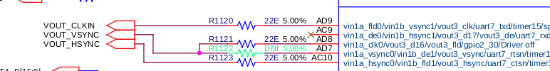
The CLK_IN,HSYNC ,VSYNC and D0-D15  are input to the encoder. The DAC1  output from ADV7393 is connected to ADA4430 filter. The output from the filter is connected to a fakra connector. We connect the signal from fakra to an Analog output device. 

For testing purpose I have done the following changes in the chains_common.c.

IN the menu I choose System Settings--> Display Settings--> Selecting 1 for selecting CHAINS_DISPLAY_TYPE_LCD_7_INCH

In the file vision_sdk/apps/src/rtos/usecases/common/chains_common.c

if(displayType == CHAINS_DISPLAY_TYPE_LCD_7_INCH)
{
pPrm->deviceId = DISPLAYCTRL_LINK_USE_LCD;
/* Changing the display port to LCD3 */
pVInfo->vencId =                                           SYSTEM_DCTRL_DSS_VENC_LCD3;                                                               //changed from  SYSTEM_DCTRL_DSS_VENC_LCD1 as display output is on LCD3
pVInfo->outputPort =                                     SYSTEM_DCTRL_DSS_DPI3_OUTPUT;                                                  // changed from SYSTEM_DCTRL_DSS_DPI1_OUTPUT

pVInfo->vencOutputInfo.dataFormat =                    SYSTEM_DF_BGR16_565;                                                                 // Changed from SYSTEM_DF_RGB24_888
pVInfo->vencOutputInfo.dvoFormat =                     SYSTEM_DCTRL_DVOFMT_GENERIC_DISCSYNC;
pVInfo->vencOutputInfo.videoIfWidth =                  SYSTEM_VIFW_16BIT;                                                                         //Changed from SYSTEM_VIFW_24BIT

pVInfo->vencOutputInfo.pixelClkPolarity =             SYSTEM_DCTRL_POLARITY_ACT_HIGH;
pVInfo->vencOutputInfo.aFmt =                             SYSTEM_DCTRL_A_OUTPUT_MAX;

/* Configure overlay params */

ovlyPrms->vencId = SYSTEM_DCTRL_DSS_VENC_LCD3;                                                                                                 //SYSTEM_DCTRL_DSS_VENC_LCD1

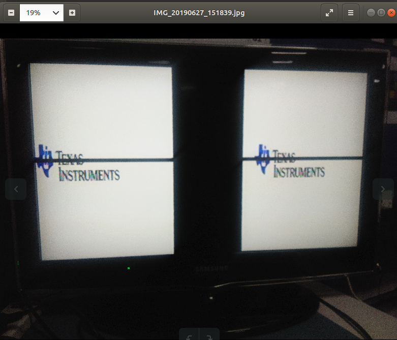
With the above changes I got 27MHz output on the clock, then I tried adding pattern generation from the ADV7393 side. I am getting a flickering display.

After reading the DSS BT656 Workaround for TDA2x.pdf I added TDM configuration.

DISPC_CONTROL1.TDMENABLE = 0x1: TDM enabled
DISPC_CONTROL1.TDMPARALLELMODE = 0x3: 16-bit parallel output selected
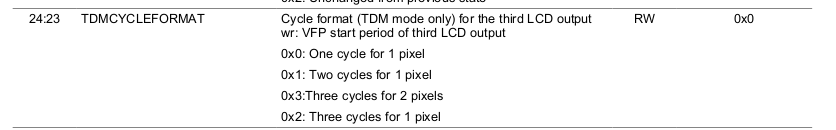
DISPC_CONTROL1.TDMCYCLEFORMAT = 0x1: 2 cycles for 1 pixel
DISPC_DATA1_CYCLE1 = 16
DISPC_DATA1_CYCLE2 = 0
DISPC_DATA1_CYCLE3 = 0

But with the changes for TDM mode resulted in ON/OFF of the display along with flickering. So I removed them again.

Am I missing anything in configuration deom TDA2P Side.

Regards,

Deepika

  • Hi,

    Can anyone provide some inputs.

    Regards,
    Deepika
  • Hi,

    I am still stuck.Has anyone worked on ADV7393 encoder.

    Regards,
    Deepika
  • Deepika,

    Set one cycle per pixel in the TDM mode.
    Also make sure that the mode-1 is used in ADV.. This is the only mode where it can be supported.

    Rgds,
    brijesh
  • Hi Brijesh,

    Thanks for reply.
    Will check and let you know.
    Also as you mentioned mode 1 in ADV, are you mentioning about the input mode i.e ED/HD-SDR Input, 16-Bit 4:2:2 YCrCb, Input Mode 001

    There is also timing mode 1 that is available . I am getting confused between the input and the timing mode.


    Regards,
    Deepika

  • Hi Brijesh,

    As mentioned in the DSS BT656 Workaround for TDA2x , instead of connecting VSYNC we need to connect FLD signal to the ADV. Right now, I am not getting any clock on the FLD line, but I am getting signal on Vsync. From Pin mux point of view , VIN1A_CLK0 pad is used for generating VOUT3_FLD. The mux mode value for this pin is coming 4. This means FLD is configured.
    Is there any other configuration in DSS to enable the FLD signal?

    Regards,
    Deepika
  • Hi Brijesh,

    Can you please help me in getting VOUT3_FLD SIGNAL?
    Pin mux value shows correct mux-mode.

    Regards,
    Deepika
  • Hi Deepika,

    Clock does not come out of FLD pin, it will be field id signal, which comes out of FLD pin. This pin is used only for interlaced output mode, so are you setting interlaced mode, ie NTSC or PAL??

    Rgds,
    Brijesh
  • Hi Brijesh,

    Actually by going through the DSS BT656 Workaround for TDA2x.pdf document, our hardware design has been changed. Instead of connecting the vsync signal from the SoC to the encoder, they have connected the FLD signal to the encoder.

    So I am not able to understand what type of output will come from the FLD signal,

    Also do I need to set NTSC or PAL output for the above scenario?? 

    Also please let me know how to set the interlaced output.

    Regards,

    Deepika

  • Deepika,

    BT656 workaround is used to connect mainly to ADV7393, which supports only NTSC and/or PAL resolution, which are interlaced resolution.

    Rgds,
    Brijesh
  • Hi Brijesh,

    What should I do with the FLD signal?I have just done pin muxing for it.

    "BT656 workaround is used to connect mainly to ADV7393, which supports only NTSC and/or PAL resolution, which are interlaced resolution"

    Ok, I will check it. Do we have any example for the same?

    Regards,
    Deepika
  • Deepika,

    I would suggest you go through that appnote and understand why and for what purpose those pins are used.

    Rgds,
    Brijesh
  • Hi Brijesh,

    Thanks for your suggestion. Will check it and keep you posted.

    Regards,
    Deepika
  • Hi Brijesh,

    I am trying to add SDTV NTSC PAL support to TDA2Px, as we need NTSC type of output. Previously I was using LCD  7-inch 800x480@60fps  type , and doing all the encoder related changes in DISPLAY_TYPE_LCD,but now to get the NTSC type of output I am adding NTSC support to TDA2px. But while doing this I am getting a lot of errors as NTSC is actually supported only for TDA3xxFamilyBuild().

    Is it possible to add NTSC support in TDA2Px?

    Regards,

    Deepika

  • Hi Brijesh,

    One more doubt, is output on LCD1 is only supported? In our custom board the ADV7393 is connected to LCD3.

    Can you please verify the below changes:

    else if((displayType == CHAINS_DISPLAY_TYPE_SDTV_NTSC) ||
    (displayType == CHAINS_DISPLAY_TYPE_SDTV_PAL))
    {
    pPrm->deviceId = DISPLAYCTRL_LINK_USE_LCD;
    pVInfo->vencId = SYSTEM_DCTRL_DSS_VENC_SDTV;
    pVInfo->outputPort = SYSTEM_DCTRL_DSS_DPI3_OUTPUT;

    pVInfo->vencOutputInfo.vsPolarity = SYSTEM_DCTRL_POLARITY_ACT_HIGH;
    pVInfo->vencOutputInfo.hsPolarity = SYSTEM_DCTRL_POLARITY_ACT_HIGH;

    /* Below are of dont care for EVM LCD */
    pVInfo->vencOutputInfo.fidPolarity = SYSTEM_DCTRL_POLARITY_ACT_HIGH;
    pVInfo->vencOutputInfo.actVidPolarity = SYSTEM_DCTRL_POLARITY_ACT_HIGH;

    pVInfo->vencDivisorInfo.divisorLCD = 1;
    pVInfo->vencDivisorInfo.divisorPCD = 1;

    pVInfo->vencOutputInfo.dataFormat = SYSTEM_DF_BGR16_565;
    pVInfo->vencOutputInfo.dvoFormat =
    SYSTEM_DCTRL_DVOFMT_GENERIC_DISCSYNC;
    pVInfo->vencOutputInfo.videoIfWidth = SYSTEM_VIFW_16BIT;

    pVInfo->vencOutputInfo.pixelClkPolarity = SYSTEM_DCTRL_POLARITY_ACT_HIGH;
    pVInfo->vencOutputInfo.aFmt = SYSTEM_DCTRL_A_OUTPUT_MAX;

    ovlyPrms->vencId = SYSTEM_DCTRL_DSS_VENC_LCD3;
    ConfigureEncoder();
    ptr=(Uint32*)0x4A0034DC;
    Vps_printf("VINA_CLK0 io: 0x4A0034DC is %x\n",(*ptr));
    pVInfo->mInfo.standard = SYSTEM_STD_NTSC;

    pVInfo->mInfo.scanFormat = SYSTEM_SF_INTERLACED;

    advTimePrms->vencId = SYSTEM_DCTRL_DSS_VENC_LCD3;
    advTimePrms->tdmEnable = TRUE;
    advTimePrms->tdmCycleFormat = 0x0;
    advTimePrms->tdmParallelMode = 0x3;
    advTimePrms->noBitsPixel1Cycle1 = 16;
    advTimePrms->noBitsPixel2Cycle1 = 0;

    }

    Regards,

    Deepika

  • Hi Brijesh,

    I am getting the following error

    [IPU1-0]
    [IPU1-0] 12.338528 s: Inside func ConfigEncoder
    [IPU1-0] 12.341914 s: Data read in 17 = 0
    [IPU1-0] 12.342493 s: Data read in 0 = 1c
    [IPU1-0] 12.343103 s: Data read in 1 = 0
    [IPU1-0] 12.343652 s: Data read in 80 = 10
    [IPU1-0] 12.344232 s: Data read in 82 = cb
    [IPU1-0] 12.344781 s: Data read in 87 = 80
    [IPU1-0] 12.345360 s: Data read in 88 = 10
    [IPU1-0] 12.346001 s: Data read in 8a = a
    [IPU1-0] 12.346092 s: VINA_CLK0 io: 0x4A0034DC is 40104
    [IPU1-0] 12.346306 s: DISPLAYCTRL: Enabled SYSTEM_DCTRL_DSS_VENC_SDTV !!!
    [IPU1-0] 12.390898 s: hal/src/vpshal_dssDispcOvly.c @ Line 1045:
    [IPU1-0] 12.390990 s: numStdModes ia 17
    [IPU1-0]
    [IPU1-0] 12.391081 s: hal/src/vpshal_dssDispcOvly.c @ Line 1084:
    [IPU1-0] 12.391142 s: Mode not supported
    [IPU1-0] 12.391234 s: dispdrv/src/vpsdrv_dctrl.c @ Line 723:
    [IPU1-0] 12.391295 s: Core control: Set Config failed!!
    [IPU1-0] 12.391356 s: Assertion @ Line: 891 in displayCtrlLink_drv.c: retVal == SYSTEM_LINK_STATUS_SOK : failed !!!
    [IPU1-0] 12.391905 s: Assertion @ Line: 891 in displayCtrlLink_drv.c: retVal == SYSTEM_LINK_STATUS_SOK : failed !!!

    Can you tell me which configuration  can be the issue.

    Regards,

    Deepika

  • Deepika, 

    You could connect to any LCD output, as long as 16bit data pins and sync/clock pins are available and are not muxed with other function.

    Rgds,

    Brijesh

  • Deepika,

    Which mode are you trying to set?

    It says the provided mode is not supported in the driver.. so provided mode is either incorrect or not supported by driver. 

    Rgds,

    Brijesh

  • Hi Brijesh,

    I am connecting it to LCD3 as the same is being used  in HW like this:

    pVInfo->vencId = SYSTEM_DCTRL_DSS_VENC_LCD3;

    pVInfo->outputPort = SYSTEM_DCTRL_DSS_DPI3_OUTPUT;

     ovlyPrms->vencId                       = SYSTEM_DCTRL_DSS_VENC_LCD3; 

    Regards,

    Deepika

  • Hi Brijesh,

    What mode is required for NTSC  output ? How to check what the current mode is set to?

    Regards,

    Deepika

  • Hi Brijesh, 

    In chains_common.c , in the function ChainsCommon_SetDctrlConfig() we have 

    pVInfo->tdmMode = DISPLAYCTRL_LINK_TDM_DISABLE;

    Are you talking about this mode?

    Regards,

    Deepika

  • Hi Brijesh,

    In the file displayCtrlLink_drv.c I found this:

    /*
    * Currently, enum SYSTEM_DCTRL_DSS_VENC_SDTV is not supported in
    * FVID interface. Hence value is overwritten as SYSTEM_DCTRL_DSS_VENC_LCD1.
    * In future once support is available, below overwriting is not needed.
    */

    So According to the current hw implementation can I do the following:

    isSdVencUsed = (Bool)TRUE;
    pVencInfo->vencId = SYSTEM_DCTRL_DSS_VENC_LCD3;??

    Regards,

    Deepika

  • Hi Deepika,

    It seems driver does not support NTSC perse, but it support 480I, can you try setting FVID2_STD_480I mode?

    In addition, you need to enable TDM mode for 16bit output mode and set the data over two pixel clock clock with entire 16bit in first clock cycles and second clock cycle just duplicates the value. 

    I am not sure if there is any driver config for the same, if not, can you check the register where we enable TDM mode and change the config directly?

    Rgds,

    Brijesh

  • Hi Brijesh,

    Thanks for your reply. I will try setting  FVID2_STD_480I  and let you know.

    I am now trying to write DISPC_CONTROL3  (0x58001848)  directly.

    "In addition, you need to enable TDM mode for 16bit output mode and set the data over two pixel clock clock with entire 16bit in first clock cycles and second clock cycle just duplicates the value. "

    Yes..this I read in the DSS workaround document for ADV7393. So according to this  TDMCYCLEFORMAT bit from DISPC_CONTROL3 should be set to 0x1 (Two cycles for 1 pixel)

    Can you please check if this is is OK?

    Regards,

    Deepika

  • Deepika,

    Yes, TDM CYCLE Format should be set to Two cycles for 1 pixel. and then, configure to send out all 16bits on first clock cycle and second clock cycles just repeats data value.

    Rgds,

    Brijesh

  • Hi Brijesh,

    In the function ChainsCommon_SetDctrlConfig(),

    else if((displayType == CHAINS_DISPLAY_TYPE_SDTV_NTSC) ||

    (displayType == CHAINS_DISPLAY_TYPE_SDTV_PAL))
    {
    pPrm->deviceId = DISPLAYCTRL_LINK_USE_LCD;
    pVInfo->vencId = SYSTEM_DCTRL_DSS_VENC_LCD3; --------------------------------------Changed it from SYSTEM_DCTRL_DSS_VENC_SDTV
    pVInfo->outputPort = SYSTEM_DCTRL_DSS_DPI3_OUTPUT;

    pVInfo->mInfo.standard = SYSTEM_STD_480I;   --------------------------------Changed this from SYSTEM_STD_NTSC as suggested
    pVInfo->mInfo.scanFormat = SYSTEM_SF_INTERLACED;

    Even after changing the above two I am getting the same error:


    [IPU1-0] 17.832702 s: hal/src/vpshal_dssDispcOvly.c @ Line 1045:
    [IPU1-0] 17.832794 s: numStdModes is 17
    [IPU1-0]
    [IPU1-0] 17.832916 s: hal/src/vpshal_dssDispcOvly.c @ Line 1084:
    [IPU1-0] 17.832977 s: Mode not supported
    [IPU1-0] 17.833068 s: dispdrv/src/vpsdrv_dctrl.c @ Line 723:
    [IPU1-0] 17.833160 s: Core control: Set Config failed!!
    [IPU1-0] 17.833221 s: Assertion @ Line: 891 in displayCtrlLink_drv.c: retVal == SYSTEM_LINK_STATUS_SOK : failed !!!
    [IPU1-0] 17.833709 s: Assertion @ Line: 891 in displayCtrlLink_drv.c: retVal == SYSTEM_LINK_STATUS_SOK : failed !!!

    Can you please suggest what is causing the mode issue?

    Regards,

    Deepika

  • Hi Deepika,

    Are you still looking into this issue?

    Rgds,

    Brijesh

  • Hi Brijesh,

    Yes, I am still stuck here. I am still debugging it.

    Regards,

    Deepika

  • Hi Brijesh,

    I am now able to get some form of output from the ADV7393.i am getting the output as below. 

    TI Logo is blue as the Blue and Red lines are swapped from Hardware. But I am not able to understand that how am I getting a same image twice on the screen.

    As the ADV7393 is connected to LCD3 the  DISP_CONTROL3 the value of  0x58001848 is 0x120.

    Can you please suggest some clues.

    Regards,

    Deepika

  • Hi Brijesh,

    Can you please provide some solution for this?

    Regards,

    Deepika

  • Hi, 

    Can anyone please help me in this. I am stuck here.

    Deepika

  • Hi All,

    A gentle reminder.

    Thanks

    Deepika

  • Hi All,

    Can anyone please help me. I am not able to fix it. Has anyone interfaced ADV7393 with TDA2P

    Regards,

    Deepika

  • We made the changes as was suggested in the document. 

    1)Resolution- 

               displayWidth = 720;
               displayHeight = 576 ;-------- NTSC PAL Resolution
    2) In chains_common.c file
          
            width                     =   displayWidth;
            height                    =   displayHeight;
            scanFormat                =   SYSTEM_SF_PROGRESSIVE;
            pixelClock                =   13500u;//27000u;    ----------------------As 13.5MHz Pixel clock is required
            fps                       =   60U;
            hFrontPorch               =   40u;
            hBackPorch                =   40u;
            hSyncLen                  =   48u;
            vFrontPorch               =   13u;
            vBackPorch                =   29u;
            vSyncLen                  =   3u;
            vencDivisorInfo.divisorLCD      =   1;
            vencOutputInfo.dataFormat       =   SYSTEM_DF_BGR16_565;     
             vencOutputInfo.dvoFormat        =
                                        SYSTEM_DCTRL_DVOFMT_GENERIC_DISCSYNC;
            pVInfo->vencOutputInfo.videoIfWidth     =   SYSTEM_VIFW_16BIT;   
            pVInfo->vencOutputInfo.pixelClkPolarity =   SYSTEM_DCTRL_POLARITY_ACT_HIGH;
    3)  In displayCtrlLink_drv.c  file 
            Vps_DssDispcAdvLcdTdmConfig advTdmPrms;
                VpsDssDispcAdvLcdTdmConfig_init(&advTdmPrms);
                advTdmPrms.tdmEnable = TRUE;
                advTdmPrms.tdmCycleFormat = 0x1;
                advTdmPrms.tdmParallelMode = 0x3;
                advTdmPrms.noBitsPixel1Cycle1 = 16;
                advTdmPrms.noBitsPixel2Cycle1 = 0;
    After the above settings the DISPC3 Register read the following: 
     DISP_CONTROL3 (0x58001848) is f00120
    DISPC_TIMING_H3 (0x58001840) is 4f04f5f
    I am attaching the image which is output.It is flickering,it seems there is some overlapping of frames which is causing the image to flicker.
    4)The encoder configurations is mentioned below:
    Let me know if I am missing anything from my side.
    Regards,
    Deepika
  • After changing the pixel Clock to 27000MHz I was able to get data on the display