


Hi,
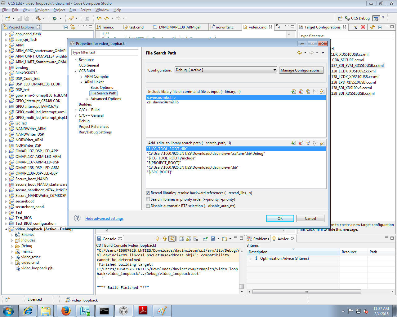
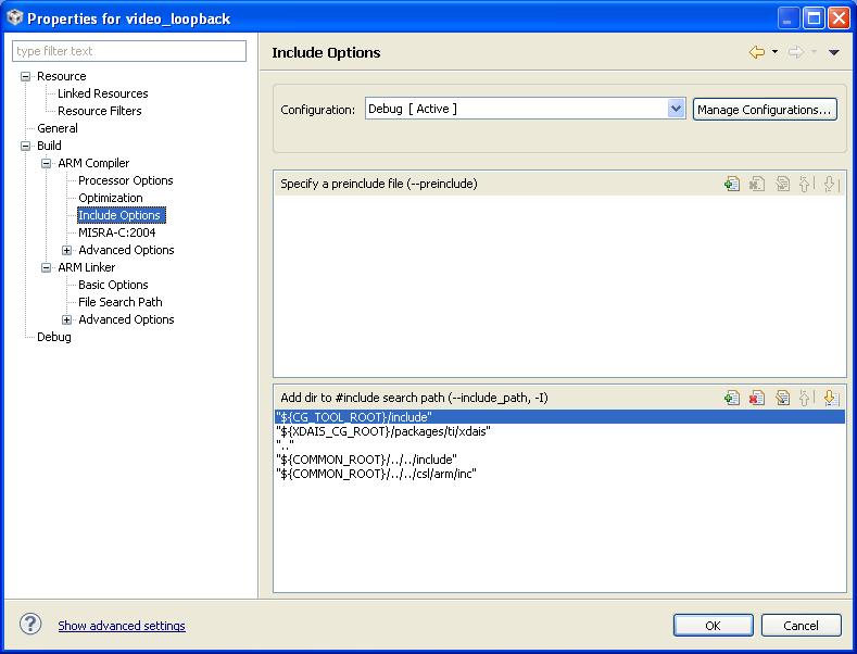
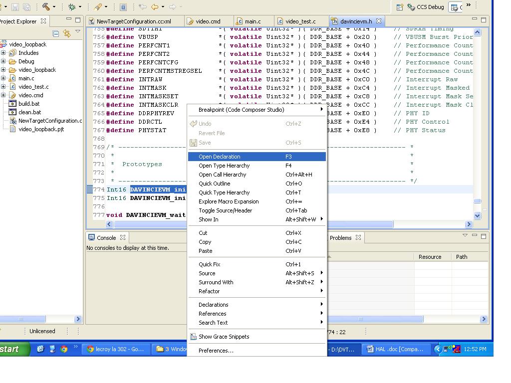
I am trying to download and debug sample video applications on Spectrum Digital davinci EVM6446 and trying a sample video loopback code given by spectrum digital(importing ccs 3 codes). when I include some c files and header files in the code, the functions are not getting linked and also I am confused with how to include the files(file path) gone through  link too. but still the same problem, can anyone suggest proper inclusion and execution of the application
tools:
CCS : Code Composer Studio 5.5.0 (for Windows XP PC)
Emulator: spectrum Digital XDS560v2 LC traveler Emulator
/*
 *  Copyright 2005 by Spectrum Digital Incorporated.
 *  All rights reserved. Property of Spectrum Digital Incorporated.
 *
 *  Not for distribution.
 */

/*
 *  Video Loopback Test
 *
 */

#include "stdio.h"
#include "davincievm.h"

/* ------------------------------------------------------------------------ *
 *                                                                          *
 *  Testing Function                                                        *
 *                                                                          *
 * ------------------------------------------------------------------------ */
void TEST_execute( Int16 ( *funchandle )( ), char *testname, Int16 ledmask )
{
    Int16 status;

    /* Display test ID */
    printf( "%02d  Testing %s...\n", ledmask, testname );

    /* Call test function */
    status = funchandle( );

    /* Check for test fail */
    if ( status != 0 )
    {
        /* Print error message */
        printf( "     FAIL... error code %d... quitting\n", status, testname );

        /* Software Breakpoint to Code Composer */
        SW_BREAKPOINT;
    }
    else
    {
        /* Print error message */
        printf( "    PASS\n", testname );
    }
}

extern Int16 video_loopback_test();

/* ------------------------------------------------------------------------ *
 *                                                                          *
 *  main( )                                                                 *
 *                                                                          *
 * ------------------------------------------------------------------------ */
void main( void )
{
    /* Initialize BSL */
    DAVINCIEVM_init( );

    TEST_execute( video_loopback_test,  "Video Loopback", 1 );

    printf( "\n***ALL Tests Passed***\n" );
    SW_BREAKPOINT;
}


/*
 *  Copyright 2005 by Spectrum Digital Incorporated.
 *  All rights reserved. Property of Spectrum Digital Incorporated.
 *
 *  Not for distribution.
 */

/*
 *  Video Loopback Test
 *
 */

#include "davincievm_i2c.h"

#define TVP5146_I2C_ADDR 0x5D

/* ------------------------------------------------------------------------ *
 *                                                                          *
 *  tvp5146_rset                                                            *
 *                                                                          *
 *      Set codec register regnum to value regval                           *
 *                                                                          *
 * ------------------------------------------------------------------------ */
void tvp5146_rset( Uint8 regnum, Uint8 regval )
{
    Uint8 cmd[2];
    cmd[0] = regnum;    // 8-bit Register Address
    cmd[1] = regval;    // 8-bit Register Data

    DAVINCIEVM_I2C_write( TVP5146_I2C_ADDR, cmd, 2 );
}

/* ------------------------------------------------------------------------ *
 *                                                                          *
 *  tvp5146_rget                                                            *
 *                                                                          *
 *      Return value of codec register regnum                               *
 *                                                                          *
 * ------------------------------------------------------------------------ */
Uint8 tvp5146_rget( Uint8 regnum )
{
    Uint8 cmd[2];

    cmd[0] = regnum;    // 8-bit Register Address
    cmd[1] = 0;         // 8-bit Register Data

    DAVINCIEVM_I2C_write( TVP5146_I2C_ADDR, cmd, 1 );
    DAVINCIEVM_I2C_read ( TVP5146_I2C_ADDR, cmd, 1 );

    return cmd[0];
}

/* ------------------------------------------------------------------------ *
 *                                                                          *
 *  tvp5146_init( )                                                         *
 *                                                                          *
 *      Initialize the TVP5146                                              *
 *                                                                          *
 * ------------------------------------------------------------------------ */
void tvp5146_init( )
{
    DAVINCIEVM_waitusec( 1000 );        // wait 1 msec

    tvp5146_rset( 0xE8, 0x02 );         // Initalize TVP5146, must do after power on
    tvp5146_rset( 0xE9, 0x00 );
    tvp5146_rset( 0xEA, 0x80 );
    tvp5146_rset( 0xE0, 0x01 );
    tvp5146_rset( 0xE8, 0x60 );
    tvp5146_rset( 0xE9, 0x00 );
    tvp5146_rset( 0xEA, 0xB0 );
    tvp5146_rset( 0xE0, 0x01 );
    tvp5146_rset( 0xE0, 0x00 );

    DAVINCIEVM_waitusec( 1000 );        // wait 1 msec

  //tvp5146_rset( 0x00, 0x05 );         // Input Video: CVBS   : VI_2_B
    tvp5146_rset( 0x00, 0x46 );         // Input Video: S-video: VI_2_C(Y) VI_1_C(C)
    tvp5146_rset( 0x02, 0x01 );         // NTSC
    tvp5146_rset( 0x34, 0x11 );         // Enabling clock & Y/CB/CR input format

    DAVINCIEVM_waitusec( 1000 );        // wait 1 msec
}

#define NTSC 1

#if NTSC
    #define BASEP_X 0x7A // 122
    #define BASEP_Y 0x12 // 18
#elif PAL
    #define BASEP_X 0x84 // 132
    #define BASEP_Y 0x16 // 22
#endif

/* ------------------------------------------------------------------------ *
 *                                                                          *
 *  vpfe_init( )                                                            *
 *                                                                          *
 *  NTSC:                                                                   *
 *      Width:  720                                                         *
 *      Height: 480                                                         *
 *                                                                          *
 *                                                                          *
 * ------------------------------------------------------------------------ */
void vpfe_init( Uint32 buffer, Uint32 width, Uint32 height )
{
    VPFE_SYN_MODE   = 0x00032F84;   // interlaced, with VD pority as negative
    VPFE_HD_VD_WID  = 0;
    VPFE_PIX_LINES  = 0x02CF020D;

    /*
     *  sph = 1, nph = 1440, according to page 32-33 of the CCDC spec
     *  for BT.656 mode, this setting captures only the 720x480 of the
     *  active NTSV video window
     */
    VPFE_HORZ_INFO  = width << 1;   // Horizontal lines
    VPFE_HSIZE_OFF  = width << 1;   // Horizontal line offset
    VPFE_VERT_START = 0;            // Vertical start line
    VPFE_VERT_LINES = height >> 1;  // Vertical lines
    VPFE_CULLING    = 0xFFFF00FF;   // Disable cullng

    /*
     *  Interleave the two fields
     */
    VPFE_SDOFST     = 0x00000249;
    VPFE_SDR_ADDR   = buffer;
    VPFE_CLAMP      = 0;
    VPFE_DCSUB      = 0;
    VPFE_COLPTN     = 0xEE44EE44;
    VPFE_BLKCMP     = 0;
    VPFE_FPC_ADDR   = 0x86800000;
    VPFE_FPC        = 0;
    VPFE_VDINT      = 0;
    VPFE_ALAW       = 0;
    VPFE_REC656IF   = 0x00000003;

    /*
     *  Input format is Cb:Y:Cr:Y, w/ Y in odd-pixel position
     */
    VPFE_CCDCFG     = 0x00000800;
    VPFE_FMTCFG     = 0;
    VPFE_FMT_HORZ   = 0x000002D0;
    VPFE_FMT_VERT   = 0x0000020E;
    VPFE_FMT_ADDR0  = 0;
    VPFE_FMT_ADDR1  = 0;
    VPFE_FMT_ADDR2  = 0;
    VPFE_FMT_ADDR3  = 0;
    VPFE_FMT_ADDR4  = 0;
    VPFE_FMT_ADDR5  = 0;
    VPFE_FMT_ADDR6  = 0;
    VPFE_FMT_ADDR7  = 0;
    VPFE_PRGEVEN_0  = 0;
    VPFE_PRGEVEN_1  = 0;
    VPFE_PRGODD_0   = 0;
    VPFE_PRGODD_1   = 0;
    VPFE_VP_OUT     = 0x041A2D00;
    VPFE_PCR        = 0x00000001;   // Enable CCDC
}

/* ------------------------------------------------------------------------ *
 *                                                                          *
 *  vpbe_init( )                                                            *
 *                                                                          *
 *  NTSC:                                                                   *
 *      Width:  720                                                         *
 *      Height: 480                                                         *
 *                                                                          *
 *                                                                          *
 * ------------------------------------------------------------------------ */
void vpbe_init( Uint32 buffer, Uint32 width, Uint32 height, Uint32 cb_enable )
{
    /*
     * Setup VPBE
     */
    VPSS_CLK_CTRL   = 0x00000018;   // Enable DAC and VENC clock, both at 27 MHz
    VPBE_PCR        = 0;            // No clock div, clock enable

    /*
     * Setup OSD
     */
    OSD_MODE        = 0x000000fc;   // Blackground color blue using clut in ROM0
    OSD_OSDWIN0MD   = 0;            // Disable both osd windows and cursor window
    OSD_OSDWIN1MD   = 0;
    OSD_RECTCUR     = 0;

    OSD_VIDWIN0OFST = width >> 4;
    OSD_VIDWIN0ADR  = buffer;
    OSD_BASEPX      = BASEP_X;
    OSD_BASEPY      = BASEP_Y;
    OSD_VIDWIN0XP   = 0;
    OSD_VIDWIN0YP   = 0;
    OSD_VIDWIN0XL   = width;
    OSD_VIDWIN0YL   = height >> 1;
    OSD_MISCCTL     = 0;

    OSD_VIDWINMD    = 0x00000003;   // Disable vwindow 1 and enable vwindow 0
                                    // Frame mode with no up-scaling

    /*
     *  Setup VENC
     */
    VENC_VMOD       = 0x00000003;   // Standard NTSC interlaced output
    VENC_VDPRO      = cb_enable << 8;
    VENC_DACTST     = 0;
    VENC_DACSEL     = 0x00004210;
}


/* ------------------------------------------------------------------------ *
 *                                                                          *
 *  video_loopback_test( )                                                  *
 *                                                                          *
 *                                                                          *
 *                                                                          *
 * ------------------------------------------------------------------------ */
Int16 video_loopback_test( )
{
    tvp5146_init( );
    vpfe_init( 0x81000000, 720, 480 );      // Setup Front-End
    vpbe_init( 0x81000000, 720, 480, 0 );   // Setup Back-End

    return 0;
}
/*
 *  Copyright 2005 by Spectrum Digital Incorporated.
 *  All rights reserved. Property of Spectrum Digital Incorporated.
 *
 *  Not for distribution.
 */

/*
 *  Board Setup
 *
 */

#include "davincievm.h"
#include "davincievm_ddr.h"
#include "davincievm_emif.h"
#include "davincievm_gpio_exp.h"
#include "davincievm_i2c.h"
#include "davincievm_msp430.h"
#include "davincievm_pll.h"
#include "davincievm_pmx.h"
#include "davincievm_psc.h"

/* ------------------------------------------------------------------------ *
 *                                                                          *
 *  DAVINCIEVM_initPscPllMemory( )                                          *
 *                                                                          *
 *      Setup the PSC, PLL, & Memory                                        *
 *                                                                          *
 * ------------------------------------------------------------------------ */
Int16 DAVINCIEVM_initPscPllMemory( )
{
    DAVINCIEVM_initPsc( );                  // Setup PSC
    DAVINCIEVM_enableAllPowerModules( );    // Enable all power modules

    DAVINCIEVM_enablePll1( 0, 16 );         // Setup Pll1 ( Clk @ 459 MHz )
    DAVINCIEVM_enablePll2( 0, 19, 9, 1 );   // Setup Pll2 ( DDR @ 135 MHz )

    DAVINCIEVM_DDR_init( );                 // Setup DDR2
    DAVINCIEVM_EMIF_init( );                // Setup EMIF

    return 0;
}

/* ------------------------------------------------------------------------ *
 *                                                                          *
 *  DAVINCIEVM_init( )                                                      *
 *                                                                          *
 *      Setup I2C, MSP430, & GPIO_EXP                                       *
 *                                                                          *
 * ------------------------------------------------------------------------ */
Int16 DAVINCIEVM_init( )
{
    DAVINCIEVM_PMX_init( );                 // Setup Pin Mux

    /*
     *  PSC, PLL, DDR, & AEMIF are already configured in the GEL file
     *  However the function _initPscPllMemory can be called to perform
     *  the same effect as the GEL files.
     *
     */
    //DAVINCIEVM_initPscPllMemory( );

    DAVINCIEVM_I2C_init( );                 // Setup I2C
    DAVINCIEVM_MSP430_open( );              // Setup MSP430
    DAVINCIEVM_GPIO_EXP_init( );            // Setup GPIO Expander

    return 0;
}

/* ------------------------------------------------------------------------ *
 *                                                                          *
 *  DAVINCIEVM_wait( delay )                                                *
 *                                                                          *
 *      Wait in a software loop                                             *
 *                                                                          *
 * ------------------------------------------------------------------------ */
void DAVINCIEVM_wait( Uint32 delay )
{
    volatile Uint32 i;
    for ( i = 0 ; i < delay ; i++ );
}

/* ------------------------------------------------------------------------ *
 *                                                                          *
 *  DAVINCIEVM_waitusec( usec )                                             *
 *                                                                          *
 *      Wait in a software loop for X microseconds                          *
 *                                                                          *
 * ------------------------------------------------------------------------ */
void DAVINCIEVM_waitusec( Uint32 usec )
{
    #ifdef ARM_SIDE

        DAVINCIEVM_wait( ( usec * 51 ) >> 6 );

    #elif DSP_SIDE

        DAVINCIEVM_wait( ( usec * 28 ) );

    #endif
}
/*
* Copyright 2005 by Spectrum Digital Incorporated.
* All rights reserved. Property of Spectrum Digital Incorporated.
*
* Not for distribution.
*/
/*
* I2C implementation
*
*/
#include "davincievm_i2c.h"
/* ------------------------------------------------------------------------ *
* *
* DAVINCIEVM_I2C_init( ) *
* *
* Enable and initalize the I2C module *
* *
* The I2C clk is set to run at 20 KHz *
* *
* ------------------------------------------------------------------------ */
Int16 DAVINCIEVM_I2C_init( )
{
#ifdef ARM_SIDE
CSL_Status status;
CSL_I2cClkSetup i2c_clksetup;
CSL_I2cHwSetup i2c_hwsetup;
CSL_I2cParam i2c_param;
CSL_i2cInit( 0 );
i2c_handle = CSL_i2cOpen( &i2c_obj, 0, &i2c_param, &status );
i2c_clksetup.prescalar = 26;
i2c_clksetup.clklowdiv = 20;
i2c_clksetup.clkhighdiv = 20;
i2c_hwsetup.mode = 1; // 0: Slave mode 1: Master mode
i2c_hwsetup.dir = 0; // 0: Rx mode 1: Tx mode
i2c_hwsetup.addrMode = 0; // 0: 7-bit mode 1: 10-bit mode
i2c_hwsetup.sttbyteen = 0; // 0: Normal mode 1: Start byte mode
i2c_hwsetup.ownaddr = 0; // #: Own address
i2c_hwsetup.ackMode = 0; // 0: ACK mode 1: NACK mode
i2c_hwsetup.runMode = 1; // 0: No Free run mode 1: Free run mode
i2c_hwsetup.repeatMode = 0; // 0: No repeat mode 1: Repeat mode
i2c_hwsetup.loopBackMode = 0; // 0: No loopback 1: Loopback mode
i2c_hwsetup.freeDataFormat = 0; // 0: No Free data fmt 1: Free data fmt
i2c_hwsetup.resetMode = 0; // 0: Reset 1: Out of reset
i2c_hwsetup.bcm = 0; // 0: Not compatible 1: Compatible
i2c_hwsetup.inten = 0; // #: Intr enable mask
i2c_hwsetup.clksetup = &i2c_clksetup;
status = CSL_i2cHwSetup( i2c_handle, &i2c_hwsetup );
CSL_i2cHwControl( i2c_handle, CSL_I2C_CMD_OUTOFRESET, 0 );
return 0;
#elif DSP_SIDE
I2C_ICMDR = 0; // Reset I2C
I2C_ICPSC = 26; // Config prescaler for 27MHz
I2C_ICCLKL = 5; // Config clk LOW for 50kHz
I2C_ICCLKH = 5; // Config clk HIGH for 50kHz
I2C_ICMDR |= ICMDR_IRS; // Release I2C from reset
return 0;
#endif
}
/* ------------------------------------------------------------------------ *
* *
* DAVINCIEVM_I2C_close( ) *
* *
* ------------------------------------------------------------------------ */
Int16 DAVINCIEVM_I2C_close( )
{
#ifdef ARM_SIDE
CSL_i2cHwControl( i2c_handle, CSL_I2C_CMD_RESET, 0 );
CSL_i2cClose( i2c_handle );
return 0;
#elif DSP_SIDE
I2C_ICMDR = 0; // Reset I2C
return 0;
#endif
}
/* ------------------------------------------------------------------------ *
* *
* DAVINCIEVM_I2C_reset( ) *
* *
* *
* *
* ------------------------------------------------------------------------ */
Int16 DAVINCIEVM_I2C_reset( )
{
DAVINCIEVM_I2C_close( );
DAVINCIEVM_I2C_init( );
return 0;
}
/* ------------------------------------------------------------------------ *
* *
* DAVINCIEVM_I2C_write( i2caddr, data, len ) *
* *
* I2C write in Master mode *
* *
* i2caddr <- I2C slave address *
* data <- I2C data ptr *
* len <- # of bytes to write *
* *
* ------------------------------------------------------------------------ */
Int16 DAVINCIEVM_I2C_write( Uint16 i2caddr, Uint8* data, Uint16 len )
{
Uint16 i;
Int32 timeout = 0x20000;
Int32 timecount = 0;
#ifdef ARM_SIDE
Uint16 response;
CSL_i2cHwControl( i2c_handle, CSL_I2C_CMD_SET_DATA_COUNT, &len );
CSL_i2cHwControl( i2c_handle, CSL_I2C_CMD_SET_SLAVE_ADDR, &i2caddr );
CSL_i2cHwControl( i2c_handle, CSL_I2C_CMD_DIR_TRANSMIT, 0 );
CSL_i2cHwControl( i2c_handle, CSL_I2C_CMD_START, 0 );
DAVINCIEVM_wait( 10 );
for ( i = 0 ; i < len ; i++ )
{
CSL_i2cWrite( i2c_handle, &data[i] );
timecount = 0;
do
{
CSL_i2cGetHwStatus( i2c_handle, CSL_I2C_QUERY_TX_RDY, &response );
timecount++;
if ( timecount >= timeout )
{
DAVINCIEVM_I2C_reset( );
return 1000;
}
} while( response == 0 );
}
//CSL_i2cHwControl( i2c_handle, CSL_I2C_CMD_STOP, 0 );
return 0;
#elif DSP_SIDE
I2C_ICCNT = len; // Set len
I2C_ICSAR = i2caddr; // Set I2C slave address
I2C_ICMDR = ICMDR_STT // Config for master write
| ICMDR_TRX
| ICMDR_MST
| ICMDR_IRS
| ICMDR_FREE
;
DAVINCIEVM_wait( 10 ); // Short delay
for ( i = 0 ; i < len ; i++ )
{
I2C_ICDXR = data[i]; // Write
timecount = 0;
do
{
timecount++;
if ( timecount >= timeout )
{
DAVINCIEVM_I2C_reset( );
return 1000;
}
} while ( ( I2C_ICSTR & ICSTR_ICXRDY ) == 0 );// Wait for Tx Ready
}
I2C_ICMDR |= ICMDR_STP; // Generate STOP
return 0;
#endif
}
/* ------------------------------------------------------------------------ *
* *
* DAVINCIEVM_I2C_read( i2caddr, data, len ) *
* *
* I2C read in Master mode *
* *
* i2caddr <- I2C slave address *
* data <- I2C data ptr *
* len <- # of bytes to write *
* *
* ------------------------------------------------------------------------ */
Int16 DAVINCIEVM_I2C_read( Uint16 i2caddr, Uint8* data, Uint16 len )
{
Uint16 i;
Int32 timeout = 0x20000;
Int32 timecount = 0;
#ifdef ARM_SIDE
Uint16 response;
CSL_i2cHwControl( i2c_handle, CSL_I2C_CMD_SET_DATA_COUNT, &len );
CSL_i2cHwControl( i2c_handle, CSL_I2C_CMD_SET_SLAVE_ADDR, &i2caddr );
CSL_i2cHwControl( i2c_handle, CSL_I2C_CMD_DIR_RECEIVE, 0 );
CSL_i2cHwControl( i2c_handle, CSL_I2C_CMD_START, 0 );
DAVINCIEVM_wait( 10 );
for ( i = 0 ; i < len ; i++ )
{
timecount = 0;
do
{
CSL_i2cGetHwStatus( i2c_handle, CSL_I2C_QUERY_RX_RDY, &response );
timecount++;
if ( timecount >= timeout )
{
DAVINCIEVM_I2C_reset( );
return 1000;
}
} while( response == 0 );
CSL_i2cRead( i2c_handle, &data[i] );
}
//CSL_i2cHwControl( i2c_handle, CSL_I2C_CMD_STOP, 0 );
return 0;
#elif DSP_SIDE
I2C_ICCNT = len; // Set len
I2C_ICSAR = i2caddr; // Set I2C slave address
I2C_ICMDR = ICMDR_STT // Config for master read
| ICMDR_MST
| ICMDR_IRS
| ICMDR_FREE
;
for ( i = 0 ; i < len ; i++ )
{
timecount = 0;
do
{
timecount++;
if ( timecount >= timeout )
{
DAVINCIEVM_I2C_reset( );
return 1000;
}
} while ( ( I2C_ICSTR & ICSTR_ICRRDY ) == 0 );// Wait for Rx Ready
data[i] = I2C_ICDRR; // Read
}
I2C_ICMDR |= ICMDR_STP; // Generate STOP
return 0;
#endif
}
/* ------------------------------------------------------------------------ *
* *
* DAVINCIEVM_I2C_read_variable( i2caddr, data, len ) *
* *
* I2C read in Master mode *
* *
* i2caddr <- I2C slave address *
* data <- I2C data ptr *
* len <- # of bytes to write *
* *
* ------------------------------------------------------------------------ */
Int16 DAVINCIEVM_I2C_read_variable( Uint16 i2caddr, Uint8* data, Uint16 len )
{
Uint16 i;
Int32 timeout = 0x20000;
Int32 timecount = 0;
#ifdef ARM_SIDE
Uint16 response;
CSL_i2cHwControl( i2c_handle, CSL_I2C_CMD_SET_DATA_COUNT, &len );
CSL_i2cHwControl( i2c_handle, CSL_I2C_CMD_SET_SLAVE_ADDR, &i2caddr );
CSL_i2cHwControl( i2c_handle, CSL_I2C_CMD_DIR_RECEIVE, 0 );
CSL_i2cHwControl( i2c_handle, CSL_I2C_CMD_START, 0 );
DAVINCIEVM_wait( 10 );
for ( i = 0 ; i < len ; i++ )
{
if ( i == 1 )
{
len = data[0];
CSL_i2cHwControl( i2c_handle, CSL_I2C_CMD_SET_DATA_COUNT, &len );
}
timecount = 0;
do
{
CSL_i2cGetHwStatus( i2c_handle, CSL_I2C_QUERY_RX_RDY, &response );
timecount++;
if ( timecount >= timeout )
{
DAVINCIEVM_I2C_reset( );
return 1000;
}
} while( response == 0 );
CSL_i2cRead( i2c_handle, &data[i] );
}
//CSL_i2cHwControl( i2c_handle, CSL_I2C_CMD_STOP, 0 );
return 0;
#elif DSP_SIDE
I2C_ICCNT = len; // Set len
I2C_ICSAR = i2caddr; // Set I2C slave address
I2C_ICMDR = ICMDR_STT // Config for master read
| ICMDR_MST
| ICMDR_IRS
| ICMDR_FREE
;
for ( i = 0 ; i < len ; i++ )
{
if ( i == 1 )
{
len = data[0];
I2C_ICCNT = len; // Set len
}
timecount = 0;
do
{
timecount++;
if ( timecount >= timeout )
{
DAVINCIEVM_I2C_reset( );
return 1000;
}
} while ( ( I2C_ICSTR & ICSTR_ICRRDY ) == 0 );// Wait for Rx Ready
data[i] = I2C_ICDRR; // Read
}
I2C_ICMDR |= ICMDR_STP; // Generate STOP
return 0;
#endif
}
http://c6000.spectrumdigital.com/davincievm/revf/
Regards.


