This thread has been locked.

If you have a related question, please click the "Ask a related question" button in the top right corner. The newly created question will be automatically linked to this question.

AM5718: Ethernet LED polarity on IDK

Part Number: AM5718

Hi,

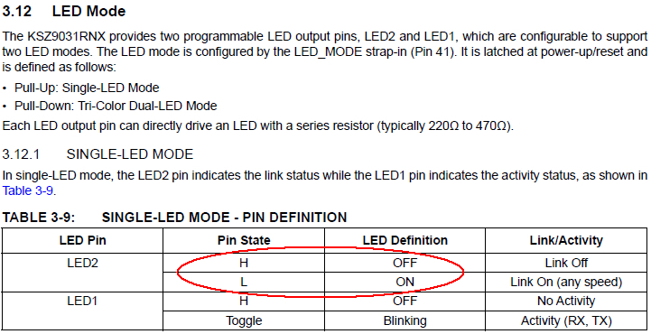
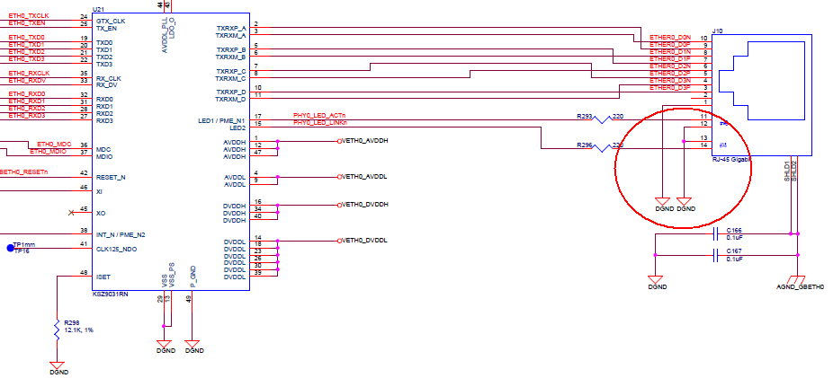
It seems that the LED polarity of the Gigabit Ethernet Link and Activity LED might be wrong on the AM571x IDK EVM (J12, U24 and J10, U21). KSZ9031RNX turns-on the LED's with a logic "L". I could not find a register in the PHY that can change polarity of the LED's.
Can someone from the EVM team please confirm or deny.

Thanks and best regards,
Patrick

  • Hi,

    The IDK is correct. This PHY has two modes for the LED pins. See the KSZ9031RN datasheet for details.
  • Biser,

    True that there are two LED modes. But that in my opinion does not change the polarity of the LED. LED Definition "On" is always with a logic low level. That means the LED should have been tied to VETH0_DVDDH instead of DGND. I'm quite shure that the LED's are on after power up even without a valid link. Bur maybe I have overseen a setting that can change polarity.
    Concerning the LED_MODE: Maybe there is also missing a Pull-Up or Pull-Down resistor on Pin 41 to set either Single-LED mode or Tri-color dual-LED mode. I have not seen a default strap when no resistor is used.

    Regards,
    Patrick
  • Patrick,

    Please refer to the following Known Deficiency listed in the Appendix of the AM571x Industrial Development Kit (IDK) Evaluation Module (EVM) Hardware  User's Guide (SPRUI97A).  I believe it addresses your concern.

    A.14 PHY address LSB for U9 and U15 can be latched incorrectly

    The PHY address LSB for U9 and U15 gets determined by the signal level at the PHY's COL pin during

    reset release. The PHY has a pull-down resistor connected to this pin to enable latching the value of 0.

    Unfortunately, this pin is also connected to one of the RJ-45 connector LEDs that pulls the signal to an

    undefined voltage of about 1.4V during the reset time. Therefore, the PHY address can incorrectly latch a

    value of 1. The LED circuit should be configured for active-high indication and the connections to the LED

    reversed with the cathode connected to ground. This allows the LSB of the address to be properly latched.

    Please refer to Section 6 of the TLK1XX Design and Layout Guide Application Report (SLVA531) for more

    information. The current software workaround programs the RXLINK pin with a pull-down resistor and then

    pulses the PHY reset from a GPIO, to cause it to latch the PHY address correctly.

    Tom

  • Tom,

    No, I'm talking about the Gigabit Ethernet LED's around U21 and U24. In my opinion the following does not match:

    Regards,
    Patrick

  • Patrick,

    I agree with your assessment.  Pin 41 should have a pull-up resistor attached and the LEDs should be properly connected with the anodes to VCC so that they turn on when the status output pin goes low as shown in the table.  We will add this to the documentation.

    Tom