Hello support Team,
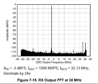
I have below query regarding the given Rx spectrum with different input amplitude Ain (such as -3 dBFS , -6 dBFS , -12 dBFS , -60 dBFS) . I have attached one of the screenshot as below.
From the given graphs of DDC output amplitude vs DDC output frequency , What I understand is that , here the Ain is given from -60 dBFS to -3 dBFS for 30 MHz input frequency . As we can consider the required default full scale range of ADC is 0 dBm ( as given in the datasheet = min full scale ADC range is -2.2 dBm( DSA=0 ) for 30 MHz) .
1) the input is given from -60 dBFS ( -60 dBm ) to -3 DBFS ( -3 dBm) as we here consider the default full scale ADC range is 0 dBm. So, here the input range of -60 dBm to -3 dBm is converted to 0 dBm using external Amplifier (bypass/enable) , internal DSA value to provide constant default full scale amplitude of 0 dBm to the ADC input. and all DDC losses are also compensated inbuilt . By using AGC Mechanism , the value of internal DSA, and external amplifier status, the below graph is providing the actual RF input given to the input and compensating all the external , internal gains and losses .
Is my understanding correct for the below given graphs of DDC output amplitude vs frequency ? Please support and provide guidance.
2) And if yes for the above , then my input dynamic range is very high , and when my input signal is low then I can use external fix low gain LNA with LNA with bypass/enable control to use AGC mechanism , but the complex thing is that my input max range is 4 dBm , so at that time, due to fix gain LNA, my input is exceeding . so can not use the above scenario.
So, I have to use variable gain amplifier instead of fix gain amplifiers to cover my full input range ( which is -36 dBm to 4 dBm) to convert to 0 dBm. So , instead of using Internal AGC mechanism , If I use external AGC control using GPIO pins then, Is it possible to compensate External VGA gain, internal DSA control to get the actual amplitude at the DDC output like internal AGC mechanism?
Please guide and support.