This thread has been locked.

If you have a related question, please click the "Ask a related question" button in the top right corner. The newly created question will be automatically linked to this question.

Map an RF input power to specific value

Hello,

 I am working on a project to protect our receiver part from unwanted input power and have some amplification on the received signal.

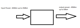
To clarify my question, I want to convert -60dbm to 20dbm to -40 to 0dbm.

I design a system with two SP4T RF switches, but it uses many components and needs a prominent space on a PCB.

I would be grateful if you could kindly let me know your suggestion to convert (-60 up to 20) dBm to (-40 up to 0) dBm.


Best regards,

John

  • Hi John,

    Could you please provide us with the below information?

    1. What is the operating frequency?
    2. High-level block diagram of the existing system
    3. A detailed range of the power levels again

    - Venkat

  • Sorry I've forgotten to mention my frequency and clarify my question very well.

    I am curious to find a circuit that can convert input signals ranging from -60dbm to 20dbm (input signal is between -60dbm to 20dbm) to output signals from -40dbm to 0dbm. It means -60dbm at input needs an amplification of 20dbm to become -40dbm, and 20db at the input needs -20db attenuation.

    Frequency: 7-8Ghz

  • Hi John,

    Thanks for providing some extra information to better answer your question. Currently, we don't have anything that supports 7-8 GHz. However, we do recommend looking at other suppliers and combining an RF attenuator, gain block or leverage a VGA depending on the insertion loss, noise, and OIP3 requirements. 

    - Venkat