Other Parts Discussed in Thread: TRF3722, TRF372017, TRF3705
Hello,
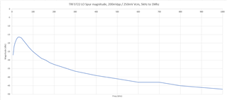
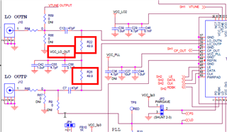
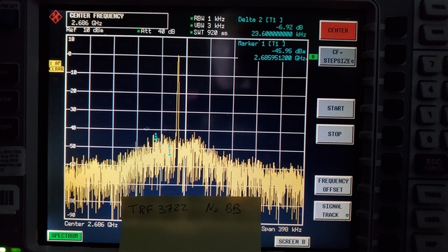
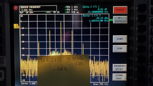
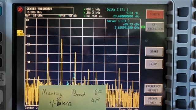
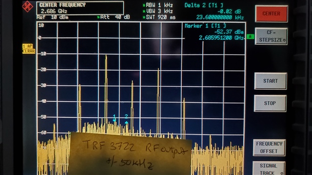
I am trying to design a system using the TRF3722. I have a PCB in hand with our design, and have also evaluated the TRF3722 and TRF372017 using the EVM moduels. I have a 50kHz I/Q single frequency input and am using a 2.0-3.0GHz PLL frequency (though many of my tests are done at 2.686 GHz, for no particular reason). I am seeing -13dBc of the IQ signal on the LO output. The LO output should, in theory, just be a single spur at the PLL frequency. I feel like I must be doing something silly, because I would expect I/Q feedthrough to the LO signal to be less than -40 to -50 dBc. For this test I have been using an AFG, with transformers to go from single ended to balanced with the ability to adjust the bias point to the required value. (Pardon my crappy SpecAn with a dim screen). I have tested this with both my design and the eval boards.
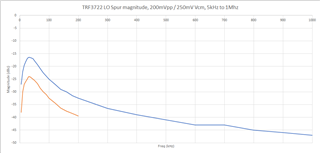
I am seeing this same behavior on the TRF372017 evaluation board.
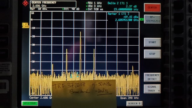
As a result of seeing baseband feedthrough to the LO, my RF output is spikey as all can be. One would expect (with a 50kHz I/Q signal, 90 degree phasing) that the resultant output would be a single spur at the PLL frequency plus (or minus depending on phasing) the 50kHz frequency of the baseband signal.
Any ideas on what I'm missing? Thanks!
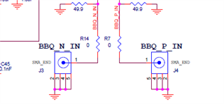
On my board all power supplies are bypassed to heck and back, ferrite isolated, and similar to the application circuitry in the datasheet. The application is using the IF frequency to analyze the return signal in DSP for accurate phase, and having the spurs really messes things up.