Part Number: AFE7950EVM
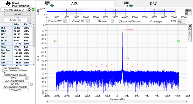
A 4.71GHz -10dBm CW signal is feeding to AFE7950EVM (NCO:4.7G)
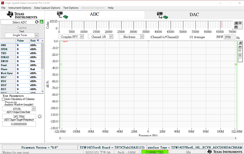
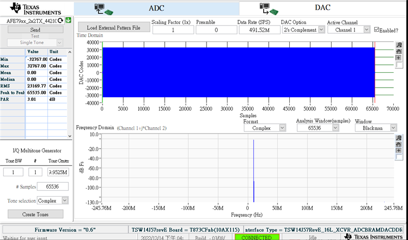
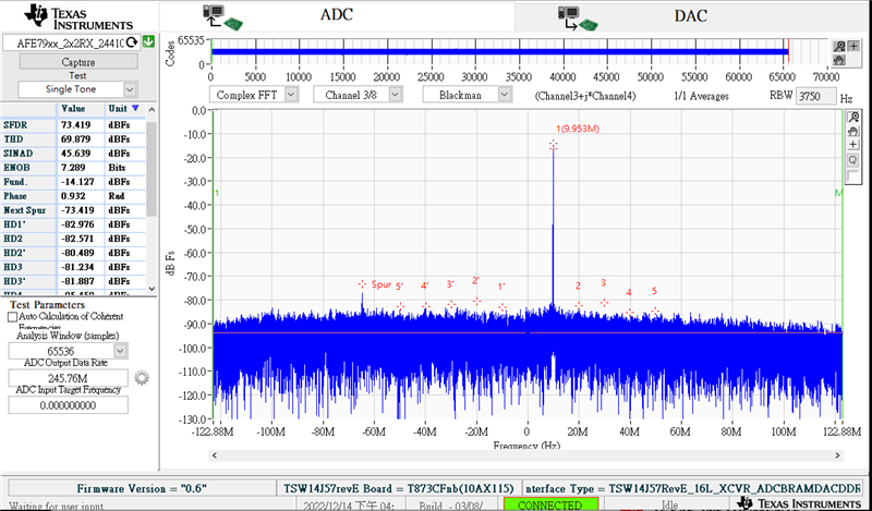
The ADC spectrum is as following pics. I tried with different window numbers.
Do you have any suggestions?


Part Number: AFE7950EVM
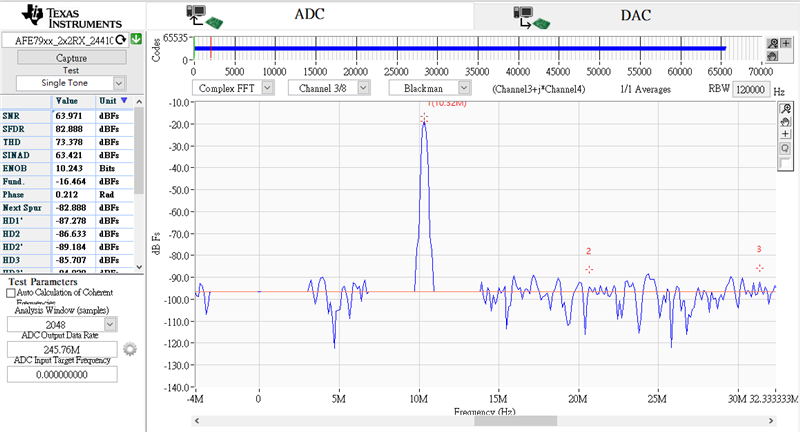
A 4.71GHz -10dBm CW signal is feeding to AFE7950EVM (NCO:4.7G)
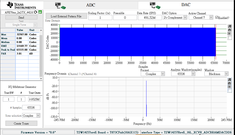
The ADC spectrum is as following pics. I tried with different window numbers.
Do you have any suggestions?