This thread has been locked.

If you have a related question, please click the "Ask a related question" button in the top right corner. The newly created question will be automatically linked to this question.

TRF370417: FSK using TRF370417

Part Number: TRF370417

Hello,

I am doing FSK modulation with TRF370417, but the output amplitude is fluctuating with respect to the input.
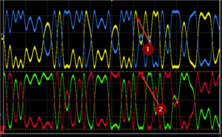
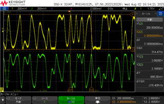
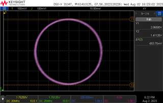
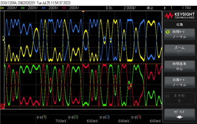
input(Oscilloscope)

input IQ waveform

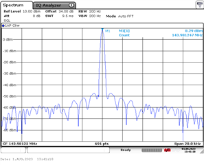
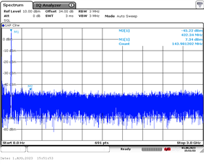
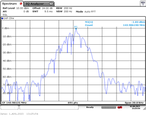
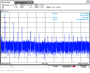
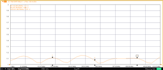
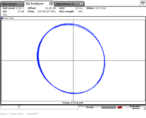
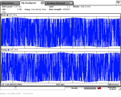
output(Signal Analyzers)

Output IQ Waveform

Is there any way to reduce fluctuations?

  • Okada-san,

    Please provide spectrum plot associated with your measurement.

    -Kang

  • Okada-san,

    Please also check your VSWR of your output circuit. The amplitude variation may be contributed from poor VSWR of your output circuit to the scope.

    -Kang

  • Kang-san,

    The spectrum of the LOP-pin input signal is as follows. The frequency is 143.98125 MHz and the power is 7 dBm.

    The spectrum of the RF_OUT-pin is as follows. The fundamental power is 2 dBm.

  • Kang-san,

    VSWR of the measurement instrument is less than 1.2.

  • Hello,

    have you ensure the peak of I signal and peak of Q signal are not overlapping. If there are overlap, there will be a net gain of the RF output signal per the basis of the quadrature modulation equation in the datasheet

    see point #1 and #2 above.

  • Kang-san,

    These are the I and Q signals; when the I signal is at its peak, the Q signal is at an intermediate voltage, and vice versa.
    Both I and Q signals are approximately 250 mVrms.
    Common-Mode Voltage is
     BBIP:1.744V
     BBIN:1.756V
     BBQP:1.744V
     BBQN:1.756V

    I and Q signals in XY plot produces a circular shape.

    The XY plot on the signal analyzer is this image.

  • Hi Okada-san,

    It is possible that the TRF370417 added additional impairments such as image and local oscillator feedthrough. This is the reason that you do not have a perfect phase/dc offset at the TRF370417 output as the I/Q signal have additional imbalance from the analog artifacts. You will need to use quadrature modulator correction technique from your signal generator to correct the I/Q imbalance. The default DC offset and I/Q imbalance specifications are listed in the datasheet. 

  • Kang-san,

    I shielded the oscillator and separated it from TRF370417 and got a good signal.

  • thank you for your update!