Hello all,
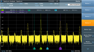
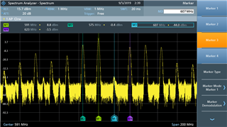
I'm currently working on a design using the modulator as an SSB upconverter. My input for IF is 16 MHz, my LO is 607 MHz to generate 591 MHz. By adjusting the IF level, pots R4, & R2 I'm able to calibrate out the LO from the spectrum. I'm running into an issue where I'm getting frequencies generated at values like Flo-2*IF.
After modeling the modulator in simulink, I was able to determine that a phase mismatch between the I & Q IF signals would cause poor upper sideband suppression. A level mismatch on the other hand would cause poor LO suppression, as proved by the sim & calibration I did.
What would cause these harmonics? I tried a very High Q 16 MHz filter & still saw these on my spectrum so it has to be something I'm doing wrong with the chip.
EDIT: Also would like to add, I am using the RF out. Did not populate my amplifier. I hand assembled this board and used a stencil & paste to get the chip on the PCB. Would a poor ground cause IF harmonics from the internal amp to come through?
Simulink Project

Spectrum Image
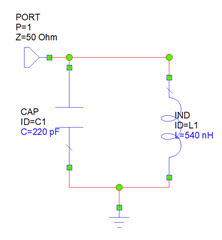
Schematic

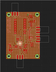
Layout