This thread has been locked.

If you have a related question, please click the "Ask a related question" button in the top right corner. The newly created question will be automatically linked to this question.

CC1120: Making signal strengths better

Part Number: CC1120

So, I'm using a CC1120 for almost an exact copy custom circuit board of the CC112xEM TI demo board at 434MHZ.  However, I'm using 0805 parts (resistors, caps, inductors) to make it easier for engineers to manufacture some prototype boards.  I'm seeing decent results on signal strength, but I'm trying to get it closer to the TI numbers I'm seeing, if possible.  The schematics of the boards are exactly the same.  The layouts, because of the size of the parts is not exact, but pretty close.  But, that pretty close might not be good enough.  I'm trying to get the impedance down in the 50 ohm range, but currently it's around 70.

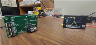
If I have 2 TI demo boards (TrxEB) exchanging packets from about 4 feet away, I get -15 to -18db signal almost every time.  That's really good for our application.  I have tweaked our custom board to where it gets -25 to -28db, but I'm trying to do better.

Our stackup was slightly different with a 20 mils substrate.   The TI board had 10 mils.  So, we adjusted that down to 10 mils, but that made the signals much worse.  So, we went back to 20 mils and made some slight adjustments to the part placement on the TX and RX lines to the antenna to come down on the impedance.  We are waiting on those prototype boards to come back.

So, I have some questions regarding other alternatives to try and some for feedback.

1. Are the 0805 parts on the RX and TX lines that susceptible to that big of a signal difference from the 0402s, everything else being the same?

2. Would it be a good experiment to try 0603s just on the RX and TX lines to see if there is any improvement?  I think our techs should be able to put those down without any new equipment.  0402s would be a little tough.

3. Why would going from a 20 mil substrate down to 10 like the TI demo board cause such a much worse performance, everything else being the same?

4. Would it be helpful to send layout files for both the TI demo board and our board for others to see what improvements might be suggested?  The layout of the TI board is online, however.

Thanks in advance.

Sutton

  • Hi Sutton,

    It sounds like you are losing 10 dB in your link budget compared to the TI boards. 

    Do you have access to a spectrum analyzer ?

    I would measure the static tx unmodulated output power with SmartRF studio as a first step.

    All our new reference designs use 0201 passives since this was the recommendation from the passive vendors that this will be the easiest to source for the next few years. Previously, for the CC1120 we used 0402 passives which is still a good option today. 

    1. Using a larger passive package size will make the layout larger and also detune the design from the original passive size that was used. CC1120 used 0402 passives. So moving to 0603 and 0805 will detune the design. Detuning occurs with a larger layout and also different characteristics of the larger passive components. From a logistics view, recommend to use 0201 or 0402. 0603 and 0805 are becoming more difficult to source especially with small values of inductance and capacitance. Finer tolerances can be achieved at smaller package sizes.

    2. 0603 will help a little instead of 0805 but the layout will still be the same. It would be better to tweek your design by going up or down to the next available component value to see if this helps. If you have followed the schematic topology, the performance should be tweeked back to optimum with some component value adjustments.

    3. & 4. Please send your layout in gerber form first then we can review the PCB stackup. Please send schematic in pdf as well.

    Regards,

       Richard 

  • How do I send files?  The insert file feature doesn't have a browse and drag and drop from a folder doesn't work.

  • Figured it out.  I have included the Gerbers for the last 3 revisions of our board.

    A5 - has produced the best results of -28db

    A6 - we reduced the stackup to perfectly match the TI board's stackup - had much worse results of -40db.  Might not see any differences from the A5.  I don't think the stackup info is in the gerbers.

    A7 - we went back to the A5 setup and repositioned some of the RX and TX parts.  Have not received this board to test yet.

    No change from A5 to A7 schematic.  Should match TI board.

    It also seems as though the TI stackup doesn't match the produced demo board.  Seems like their production parameters weren't exactly the same.  The board is thicker than it should be.  Our A6 was much thinner, which matched the TI stackup.  Just an observation.  So, not sure what stackup was produced with the boardhouse they used.

    160-4020A5_Gerbers.zip

    160-4020A6_Gerbers.zip

    160-4020A7_Gerbers.zip

    160-4020A7.pdf

  • Will review these files.

    Do you have access to a spectrum analyzer ?

  • I have a tinySA.  That shows that all packets are being broadcast at 434Mhz.  But, I don't have a better one than that.

    I should be able to borrow a better one next week.

  • Can you test with a static unmodulated Tx carrier in SmartRF studio at maximum output power and let me know what output power you are measuring ?

  • Measure the conducted harmonics as well:

    2nd harm (866 MHz)

    3rd harm (1299 MHz)

    4th harm (1732 MHz)

    5th harm (2165 MHz)

  • An unmodulated TX using the TI board and SmartRF generates a signal received by my tinySA analyzer at -30db and for our custom board at -40db.  Which is consistent with the 10db loss we are seeing.  The measured harmonic of 866 MHZ is about -80db in both cases.  My small analyzer won't go higher than 960 Mhz.  So, I can't do testing higher than that.  I hope this is what you were asking for.

  • If we take these measurements relative to each other. Then it sounds like you are missing 10 dBs on the Tx side which will also cause more than likely a 10 dB loss on the Rx side; so you are losing approx 20 dB in your link budget.

    The 2nd harmonic on your board is the same as the TI board despite your output power being 10 dB lower. So this is also a sign that the design is mismatched as well. 

    The absolute power level does not sound right when you are measuring a level of -30 dBm to -40 dBm. The TinySA can handle up to 6 dBm or 10 dBm pending model. You should set the transmitted output power to 0 dBm, then measure this level on the TinySA. Or use a 10 dB attenuator on the TinySA.

    Make sure you measure with a cable and not radiated via an antenna.

  • "So this is also a sign that the design is mismatched as well."

    Mismatched in what way? 

    Can you look at the layouts A5 & A7 I sent and see if you notice anything we should change and try?

    I'm doing more testing and we will be testing the A7 changes shortly.

  • Shall we close this ticket or do you have new conducted measurements ?

  • I was waiting for any feedback to my questions, but haven't received any.  When the output is 0db (PA_CFG2 = 0x63), a CW test with a cable connected to the TinySA gives a -25db.  See picture.  So, see my questions listed above.  The A7 changes of  slightly reorienting some parts didn't have much effect.  Also, our TX connected directly to the TI board with a cable was -9db.  And our TX connected to our RX with a cable was also -9db.

  • Have not provided much more feedback since waiting for your measurements from previous comments. 

    Are you using tweeking your component values as mentioned previously in 2. You should see output power differences when testing with different component values.

    L4 is 15 nH today. Does the output power increase when this is reduced to 12 nH ? Does the the output power decrease when testing with 18 nH ?

    Perform similar tests with L2 and then L1. Only make one change at a time and re-measure the output power.

    2. 0603 will help a little instead of 0805 but the layout will still be the same. It would be better to tweek your design by going up or down to the next available component value to see if this helps. If you have followed the schematic topology, the performance should be tweeked back to optimum with some component value adjustments.

    Your output power measurements with SmartRF studio does not seem consistent: When the output is 0db (PA_CFG2 = 0x63), a CW test with a cable connected to the TinySA gives a -25db ??

    However, this sounds more expected provided that the boards are still set to 0 dBm power setting: TX connected directly to the TI board with a cable was -9db.  And our TX connected to our RX with a cable was also -9db.

  • Thanks for the responses.  We are waiting on some parts for the tweaking.  Still haven't figured out the weird issue of why a TI board transmitting to our board gives a -20db, while all other combos gives -9db.  What is odd is that we have both a packet test and a CW test for each combo.  The TI board to our RX gives a -9 with a CW test and a -20 with a packet test.  All other combos are a perfect -9.  That one setup is a mystery.

  • We should be able to make some parts changes soon.  Meanwhile, any feedback on this test?  A TI TX board connected to our RX board gives -20db connected via cable (previous post).  All other combinations give -9db.  We took the TI radio board off the TI eval board and connected up our radio board to the TI eval board.  The value goes to -9db.  It's a mystery why the TI radio board gives such a bad reading to our RX board.

  • Hi Sutton,

    Just to add a few points to the discussion:

    Please can you summarise which measurements you have performed so far (in a table or similar)? It is easy to miss something with quite a few different points and combinations being discussed. Are all of these tests conducted measurements?

    The difference between the CW and packet test using a TI EVM for TX and your board for RX is strange; it would probably be helpful to get the exact details of how you are performing the measurements.

    Also, please refer to follwing App Note and double-check the procedures outlined in it: SWRA603 (Debugging Communication Range): https://www.ti.com/lit/swra603

    For some additional context: by changing the dielectric thickness of your PCB stackup, changing the component sizes, and any other deviations from the TI reference design you are changing the load/source impedances presented to the PA/LNA. This could result in both reduced RX performance (mainly seen as reduced RX Sensitivity) and worse TX output power/spurious emissions. Without the use of an EDA tool and/or more involved measurements it is hard to know exactly what the effects of those changes are on your board but, as you have seen, they are probably not wanted.

    If your board is showing the same harmonic power levels as the TI EVMs but the measured output power for your board is also lower, then this implies that you have increased spurious emissions as well. This could also be be caused by the change in PA load impedance, resulting in increased non-linear behaviour.

    This is what Richard meant by (impedance) mismatch; mismatch when compared to the TI reference design. Therefore, manually tweaking the matching networks to try and reach (or come close to) the original target impedances "seen" by the PA and LNA is the recommended solution here and is likely the fastest way to reach acceptable performance again given the equipment available.

    The reason Richard is waiting for the results of tuning the RF path components is that it can change the RF performance quite significantly, so until there are results from this there is limited usefulness for a lot of the other RF testing. 

    Regards,

    Zack

  • Zach,

    Thanks for the answers.  I am still experimenting with different path components.  I will detail those and better detail how our experiments are conducted.  Stay tuned.

    Sutton

  • Zack,

    Most of our dB loss had to do with only getting 3.1V as a power source to the RF chip.  When we upped that to 3.3V, the dB level was very good.  Never thought that a 20dB loss would be attributed to 0.2V less power.  So, we never looked there.  So, with a 1 ft. distance with antennas, we get the same -9dB as when connected via cable from RX to TX.  And, -20dB from 6 ft. is very adequate and fairly close to the TI demo boards of -17dB.  So, we are happy, but still experimenting.  Thanks for your input.

    Sutton