This thread has been locked.

If you have a related question, please click the "Ask a related question" button in the top right corner. The newly created question will be automatically linked to this question.

AFE7903: Noise shaping due to dithering

Part Number: AFE7903
Other Parts Discussed in Thread: AFE7900EVM, LMK05318, LMK5B12204,

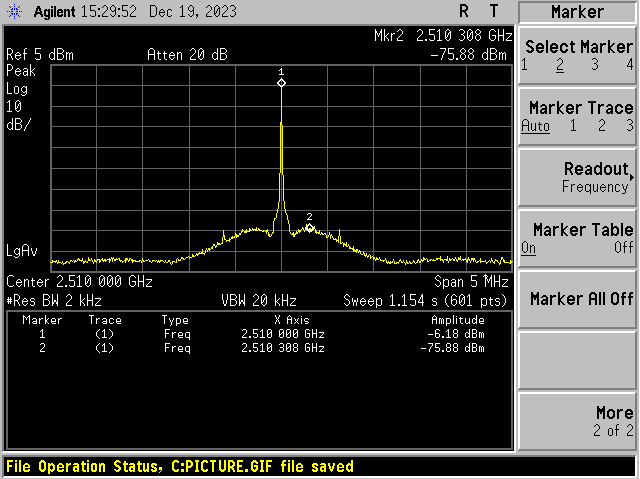
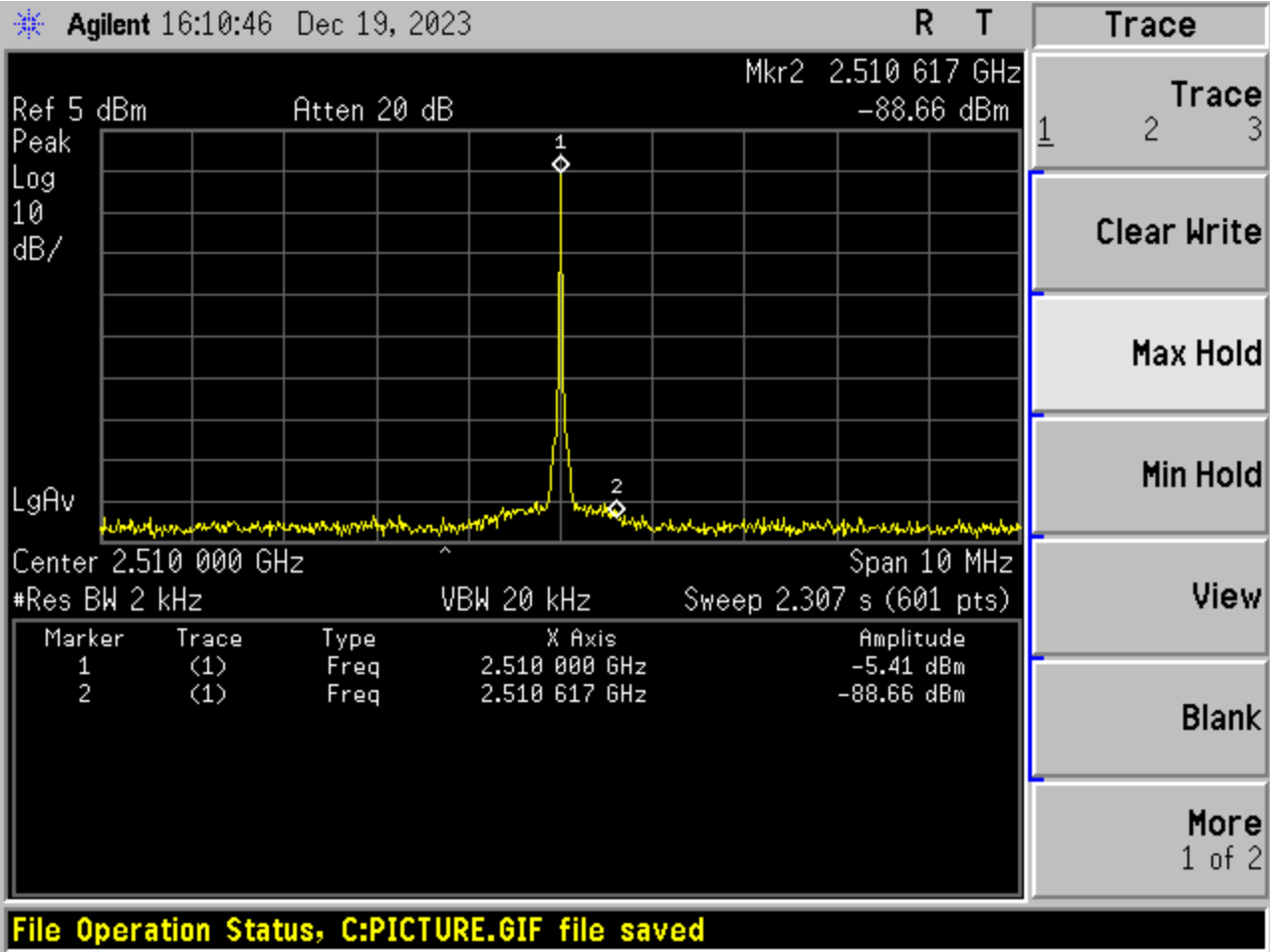
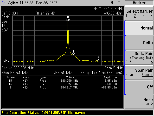
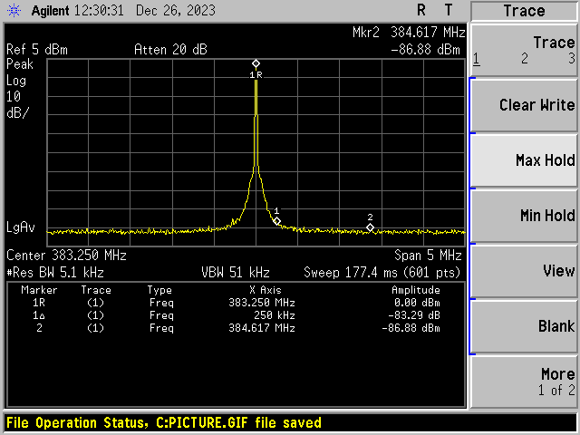
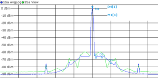
We are struggling with an unexpected noise shape around CW signals. It only appear if we use the same trx to sample the signal, process it an use the same trx to send it out. It happens with the loopback in the TRX and also happens if the loopback is done in the FPGA. Only the shape of the noise shoulder changes. If we acquire the signal or using synthetic signals to send out, we don't see such noise shoulders. Below you see an example

This noise shaping has often to do with dithering. So we played with dither register mentioned in the "AFE79xx Programming User Guide".

The bit TX_CLK_DITHERED_MODE_EN in register A0h in the JESD SubChip Register Map had an effect. If we read it back, it's set to 0x03 which means the clock is disabled and dithering is enabled. Writing a 0x03 again to this register removes the shoulders. That's weird. Writing a 1, 2 or 3 sometimes change something, generate spurs, reduces noise, destroys the signal completely or work perfect and smoothly. So I don't thinks it's a good idea to manually write to this register.

Can you explain what to do instead?

  • Hi Christian,

    Could you please provide the frequency scale for your picture to see how far to each side does the noise extend?

    Based on how close it is to the output signal, we could attribute this noise to be phase noise from the clock. I ran a quick test by setting up two AFE7900EVMs in loopback mode to show this. One is a normal EVM that gives the AFE a Fref clock from the LMK to the AFE PLL and I see the following noise shape (I am using Max hold in the spectrum analyzer):

    And the second EVM takes an external clock from a signal generator to give the DAC clock to the AFE and I can get the following:

    As you can see the clock source in this case is dominating the phase noise around the DAC output.

    For guidance on modifying the EVM to use external clock please refer to the AFE79xx_EVM_External_Clocking_Guide.pptx guide in the secure folder.

    Best,

    Camilo

  • Hi Camilo

    Your first picture looks exactly the same as our "non loopback" singal (the blue one) We also have 5 MHz span. The phase noise is dominated by our clock source. The shape of the green graph happens if we use a local loopback. 

    Maybe it has to do with the frequency settings. I will try to reproduce it on an EVM.

  • Hi Christian,

    Understood, please try using an EVM with a clean external clock source to see if the noise around the signal improves.

    Also, for my measurements I was using the AFE internal loopback mode. Just to make sure I follow. You are saying that you see the green noise shape when you also use the AFE internal loopback mode? If so, do you see the noise shape at the RX RF input?

    Best,

    Camilo

  • Hi Camilo

    I had problems to get our configuration running on the EVM. I'm now able to reproduce it. You will get the file in a private message.

    I've found a picture of our own hardware with a third signal. The orange one is with a generated tone. The green one with a loopback in the FPGA and the blue one the loopback inside the TRX. 

    The loopback signals shows a lower noise as the generated tones at some frequency offsets. This can not be related to the phase noise of the oscillator.

    The following picture is taken on the EVM with the TRX loopback and the configuration I will send you.

    The same noise shoulder appears. Maybe you will need a really good spectrum analyzer to see it. We use a FSW from R&S. The FSV aren't good enough.

    Maybe you are able to modify our configuration to use an acquisition board to generate a tone. I wasn't able to get it running on our TSW14J56.

    I will also try to get it running with an external clock, but I'm sure this won't change anything. the pictures taken on our own hardware were captured with a really bad clock. Improving the phase noise changed the level, but not the shape of the noise shoulders.

  • Hi Christian,

    I used your configuration on an AFE7900EVM that uses the clock from the LMK and got the output below using internal loopback. As you can see the shoulders are present.


    I then took your configuration, modified it to use external clock and tested it on an AFE7900EVM modified to use EXT clock. As you can see below the shoulders around the signal are gone due to the improved phase noise of the clock.


    I will provide you with the updated configuration for external clock through a private message. If you can make the modifications in the EVM I would suggest testing with a clean external clock to corroborate.

    Best,

    Camilo

  • Hi Camilo

    I know, that improving the quality of the oscillator would reduce the phase noise in general and would move the noise to a level where it doesn't matter. But for us it's not really feasible to do this, as the hardware already exists. Also the clock is good enough for us if we use the ADC of one and the DAC of another TRX. That's why we've chosen this cheap hardware solution. But now we need to process the signal and use the same TRX for ADC and DAC. And now we see these shoulders. We now have a problem. Either we need to redesign our hardware or find a fix within the TRX.

    I'm quite sure it has to do with dithering. And there are a lot of register to play with it, but no documentation. Changing X_CLK_DITHERED_MODE_EN have a positive impact, but often lead to an unusable TRX or a destroyed signal. Do you have an idea how to play with dithering?

  • Hi Christian,

    Dithering in the AFE is a setting for the digital clocks. Phase noise is dependent only on analog.

    I noticed that in your script, your Fref was 122.88MHz. Would it be possible for you to change your Fref frequency to 491.52MHz? By changing your Fref to 491.52MHz you should see an improvement in the phase noise.

    Also, what are you using as the clock source for the AFE?

    Best,

    Camilo

  • Hi Camilo

    We already tried 491.52 MHz and will use it. But this will just slightly reduce the noise level, but not the shape.

    We are using a AD9542 as clock source. And I now, your LMK5B12204 or LMK05318 would have a better phase noise. But we would like to avoid a redesign as these PLLs are really complex and switching to another PLL would take some time.

    If you look at my graphs, can you explain the different shapes of the noise? If this noise shaping with the shoulders wouldn't appear, we would achieve the necessary performance.

    Regards,

    Christian

  • Hi Christian,

    There are a couple of things that could affect the phase noise in the DAC while in loopback mode like the clock and your input signal to the RX channel.

    Could you please connect your RF source that you are inputting into the RX channel and provide what you see in the Spectrum analyzer? This is to see if those shoulders are present in your RF source.

    Do you see the same noise shape with a different signal source while using the AFE internal loopback?

    Best,

    Camilo

  • Hi Camilo

    The input signal is good. There is no such noise shoulder.

    And yes, it appears with any kind of signal. We've measured it with modulated broad band signals and different generators. You can see this also on your site if you using the configuration I sent you. But you will need a better analyzer, which can be a problem.

    I would like to capture the signal with one of your FPGA capturing cards. So I would be able to have a look at the signal quality of the ADC with a neutral HW. We have multiple tsw14j56 laying around. But with the actual SW I'm no longer able to get it run. With the prior version it worked. But all the relevant scripts are somehow broken or missing. Do you have an idea how to get it running?

  • Hi Camilo

    I've done a lot of measurements and came to a few conclusions.

    We won't be able to achieve the necessary performance with the AD9542 PLL. We need to get a better one.

    The LMK5B12204 fits our needs on the clocking architecture and has a much better phase noise. But now the AFE is the limiting factor. The following pictures shows the phase noise from the datasheet.

    The increased noise around 100-200kHz is a problem. Together with the noise shaping in the loopback situation the performance is unusable. We have to get rid of the noise shaping and/or improvements done on this noise peak. I know, using an external clock of multiple GHz would lead to drastic improvement. But this would need a second PLL and a heavy redesign of our board. So I'm left with two questions:

    1. Is it possible to reduce or remove the noise shaping?

    2. How to improve the PLL performance?

    I have already played with the TRX PLL and achieved a much better performance with an increased charge pump current. This is done with the following commands in Latte:

    AFE.regs.writeReg(0x0015,0x40)

    AFE.regs.writeReg(0x0170,0x01)

    AFE.regs.writeReg(0x0015,0x01)

    AFE.regs.writeReg(0x0040,0x60)

    Also tuning CTL_CP_BIAS (reg 0x41) or CTL_LPF_R (reg 0x43) have an impact.

    But I prefer a safer way to tune it. Is there a simulation for the PLL within PLLatinum? Is it allowed to modify the register or what is the prefered way?

  • Hi Christian,

    I will reach out to our design team with your questions. Also, just a couple of comments/questions:

    Just to make sure it is clear, what is the performance you need to achieve?

    Do you have access to a phase noise analyzer? If so, could you provide a phase noise plot of both your RF input into the RX channel of the AFE and the output from the TX channel?

    I had asked about the performance of your RF source because from the plots you showed, you only see the high shoulders when using the RX to capture the signal. Because you did not see the high shoulders when using a digital tone from the FPGA. Is my understanding correct?

    Best,

    Camilo

  • Hi Camilo

    We need to achieve a noise level of -75 dBc from 100 kHz to 250 kHz and -80 dBc from 250 kHz to 500 kHz measured with 30 kHz. Or a phase noise of 44dB lower due to the 30 kHz which leads to -119/-124. All measured around 400 MHz. Translated to the phase noise plots in the datasheet this is ~112 @ 250kHz @ 1910 MHz.

    Normally we use the SMBV100A which is clean enough.

    I've done all measurements also with a SMA100A which is much better. But this doesn't change anything. The signal is not the problem.

    The following is the phase noise of the signal while repeating. You see both noise shoulders around 250 and 800 kHz.

    I would really like to show you the performance of the generated tone. But as I switched to the EVM I'm no longer possible to do this.

    And yes, you are correct. There wasn't such a high shoulder with the tone. I'm quite sure there will be a smaller shoulder now with the improved clock, but not that high as in repeating mode.

  • Hi Camilo

    I've digged a little bit in your library and found some useful python functions.

    AFE.TOP.adjustPllLoopBw(0..15)

    This adjusts the charge pump current in a much better way than directly writing to the registers. But the python code itself is wrong for the AFE7903. So i had to patch it. The following is the patched function from mTopLib.py

    	def adjustPllLoopBw(self,factor):
    		""" higher the factor, higher is the loop bandwidth """
    		if self.systemParams.chipId==0x79 and self.systemParams.chipVersion==0x20:
    			factor_list=[0.8, 1.0, 1.2, 1.4, 1.6, 2.0, 2.4, 2.8, 3.2, 4.0, 4.8, 5.6, 6.4, 8.0, 9.6, 11.2]
    			cp_current_factor=[1,2,4,8]
    			cp_current_factor_index=[1,0,2,3]
    		else:
    			factor_list=[0.8, 1.0, 1.2, 1.4, 1.6, 2.0, 2.4, 2.8, 3.2, 4.0, 4.8, 5.0, 5.6, 6.0, 6.4, 7.0, 7.2, 8.0, 8.4, 9.6, 11.2, 12.0, 14.4, 16.8]
    			cp_current_factor=[1,2,4,5,6,8,12]
    			cp_current_factor_index=[1,0,2,5,4,3,7]
    		cp_scaling=[1,0.8,1.4,1.2]
    
    		if not 0<=factor<len(factor_list):
    			error("Incorrected Value Given.")
    			return
    		val=factor_list[factor]
    		found = False
    		for j in cp_scaling:
    			for i in cp_current_factor:
    				if round(i*j,2)==val:
    					found=True
    					break
    			if found==True:
    				break
    		self.requestPllSpiAccess(1)
    		self.regs.PLL.PLL.REGGROUP_0.Property_20h_7_5=cp_current_factor_index[cp_current_factor.index(i)]
    		self.regs.PLL.PLL.REGGROUP_0.Property_8h_19_18=cp_scaling.index(j)
    		self.requestPllSpiAccess(0)
    		#adjustPllLoopBw

  • Hi Christian,

    I will reach out to our software team in regards to this.

    You also said you were able to get better performance by changing the PLL loop bandwidth. Even with that, were you not able to meet your desired performance?

    Best,

    Camilo

  • Hi Camilo

    Yes I did. I was able to get the noise to ~5dB below the limits. That's hopefully enough. According your data sheet it's possible to get close to our limits due to  tolerances especially due to the temperature. Also the noise shapes varies, I think, due to the data delay. We see this if we do the loopback through the FPGA. That's not a cool effect and can consume a few dB more.

    In summary, the 5dB are good, but maybe not enough in all situations.

  • Hi Christian,

    I have heard back from the software team. Aside from tuning the PLL loop bandwidth there are no other settings in the AFE to improve the PLL phase noise even more.

    Best,

    Camilo

  • Hi Camilo

    Thanks for the answer. We will use a different external PLL and tune the TRX PLL. One last question. Is there any advisory how to tune the TRX PLL? I don't like to randomly play with the loop filter and have no idea if it's stable or not. It would be cool if the AFE series would appear in the PLLatinum software. Maybe you recycled one of your existing PLL designs for the AFE and it's possible to do some simulation with this part in PLLatinum.

    Best,

    Christian

  • Hi Christian,

    The default setting is guaranteed to be stable. We only provide the function so that you could check if you can get the phase noise performance you needed. Our suggestion would be to go with the default setting.

    And we do not have the model available for PLLatinum.

    Best,

    Camilo

  • Hi Camilo

    Ok, I understand.

    Thanks for your help on this topic.

    Best,

    Christian

  • Hi Christian,

    No problem.

    Best,

    Camilo

  • Hi Christian,

    I understand that this issue may still be open, so I've unlocked the thread. Would you mind please describing the current issue and what I can do to support?

    Thanks,

    Aman

  • Hi Aman

    I summarize:

    The transceiver has a noise shaping if it is used in loopback mode (TRX or FPGA). Depending on the settings this reduced our noise margin by 8 dB.

    There was no way to remove this noise shaping.

    With a nearly perfect external PLL (TI LMK5B12204 :-) we are still at the limit due to the internal PLL. Switching to design without internal PLL is not possible at the moment.

    So we need to improve the internal PLL a little bit. There we are struggling as this is not intended to be done by us.

    * No simulation for PLLatinum to verify the settings

    * Buggy adjustPllLoopBw python function

    Actually we are forced to directly modify some register which is not a satisfying solution.

  • Hi Christian,

    Thank you for the summary, this is very helpful for me! I'm working through the various issues in order of priority, but I'll check to see if we have any extra resources to adjust the internal PLL.

    Thanks,

    Aman