Other Parts Discussed in Thread: TSW14J58EVM, AFE7769D
Still I could not make the EVKit work correctly.
I want to know the setting one by one.
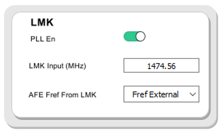
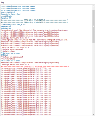
LMK default setting is as below and it could not be saved on the config file.
Should I use the default setting?
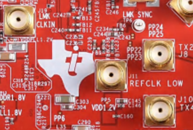
- If I use default setting, should I connect 1474.56Mhz on CLKIn(J19) port? Which level should it be?
- Default setting shows as external ref. Should I connect REF_CLK from other external Signal generator on J11? Is any additional hardware setting required?
If I use different setting from default,
- What is the possible freq of CLK IN(J19) port? Could I use 10MHz CLK from equipment on the port? What will happen if nothing connected on the CLK_In(J19) port?
- If REF internal is used, I guess I don't need to connect anything on the J11 port. Could the internal ref support all possible ref_CLK freq? Is there any limitation?