- Ask a related questionWhat is a related question?A related question is a question created from another question. When the related question is created, it will be automatically linked to the original question.
Hi expert,
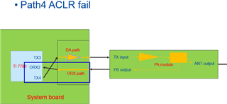
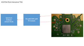
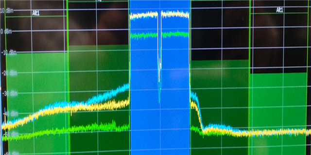
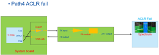
Below is the ACLR test on Tx3 and Tx4 channel from customer. They used FPGA for DPD. The HW circuit design on each channel are the same, but ACLR result is different.
The yellow waveform in the figure is connected on Tx3, the ACLR is passed. The blue waveform is connected to Tx4 but ACLR is failed.
May we know what parameters in the AFE7799 we can tune or any others factors might relate to this?
Thanks,
Allan