


Other Parts Discussed in Thread: AFE8000,
Hi,
I have two questions regarding the Tx chains of the AFE8000 EVM board:
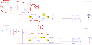
(1) I've noticed that there are values differences of caps & inductors on the AFE8000EVM board matching network:
For example -
* (TXE_OUT, J14) C498 = 3pF, C497 = 0.7nH (inductor), C352 = 1.2pF [Capacitor] ...
* (TXF_OUT, J12) C602 = 2.7pF, C501 = 2.2pF [Capacitor], C79 = 3nH (inductor) ...
What is the reason for these differences?
Is it due to the EVB layout, to compatible to the AFE8000's relevant output (5TXOUT vs 6TXOUT)?
(2) What is the reason for the 1.2v common-mode addition on the Tx signals?
Is it unique for the EVB, or a requirement of the AFE8000 component?
Please advise,
Avihay.
