This thread has been locked.

If you have a related question, please click the "Ask a related question" button in the top right corner. The newly created question will be automatically linked to this question.

AFE7950: AFE7950 9.6GHz RF Single Ended to Differential Matching

Part Number: AFE7950
Other Parts Discussed in Thread: , TRF1208

Tool/software:

The AFE datasheet provides characterization data for various configurations including 12GHz input clock and 9.6GHz RF

The evaluation modules give good reference circuitry for the single ended to differential conversion but unfortunately for this configuration.

Could you provide guidance for the 12GHz Fref and 9.6GHz RF case based on the implementation used to characterize the device in the datasheet?

  • Hi Erik,

    Please note that there are two evaluation boards that use the AFE7950.

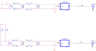
    The first board is the 'AFE7950EVM' which has similar matching networks on all channels for 9.6GHz, all using a balun. The schematic snippet that you show above are from this EVM.(In the secure folder the schematic can be found in the EVM files named 'AFE7950EVM_DesignFiles')

    The second board is the 'TRF1208-AFE7950EVM' which has different matching networks using both amplifiers and baluns for different frequencies. (In the secure folder the schematic can be found in the EVM files named 'AFE7950_TRF1208_AMPS151A')

    If you would like to see an example match for 9.6GHz I recommend referencing the 'AFE7950EVM' schematic. Also, in the OneRelease folder we include s-parameters which you can use to simulate a matching circuit that can be used as a starting point for your design. Please note that it has been seen that layout parasitics will also have an impact on the performance of your matching network considerably at higher frequencies because the terminations on the RF channels are sensitive. 

    Regards,

    David Chaparro 

  • Hello David,

    Thank you for your response. I will use the AFE7950EVM as a reference.

    There does appear to be difference between some of the channels:

    Do you know why the matching networks are not uniform?

    I have looked for the OneRelease folder in the secure documents portal and cannot find it. But I think I've found the information you were referring to in the Simulation_Models archive.

    Thanks again!

    Erik

  • Hi Erik,

    The secure site itself is called 'OneRelease' and the file that you found is correct. 

    The reason that the matching networks are not uniform is because of differences in routing on both the substrate and PCB. 

    Regards,

    David Chaparro