Tool/software:
I am trying to follow your guidance for the RF signal routing but I'm not sure which advice to adhere to.
The AFE79xx Schematic Layout Checklist states the following:
Tx is 50ohm output differential termination impedance for the AFE795x family. And 100ohm output differential termination impedance for the AFE790x family.
For 50 ohm differential impedance, 1:1 balun is needed. Each single ended trace after transformer to be 25ohm and effective differential impedance of 50 ohms.
The AFE79xx Layout Guide recommends 50ohm differential to 50ohm single ended for the TXDAC outputs:
The differential RF traces must be routed as 100-Ω CPWG (coplanar waveguide with lower ground plane) or microstrip. The TXDAC outputs are routed as 50-Ω based CPWG from the TXDAC output to the balun, and then 50-Ω single-ended from the balun to the SMA connectors.
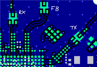
The AFE7950EVM layout uses the same differential sizing for all three RF groups (RX, FB, and TX):
 \
\
Could you direct us towards the proper routing standard assuming we are using the same matching circuit as the EVM?

