This thread has been locked.

If you have a related question, please click the "Ask a related question" button in the top right corner. The newly created question will be automatically linked to this question.

AFE7901: Input impedance vs Frquency

Part Number: AFE7901
Other Parts Discussed in Thread: AFE7900

Tool/software:

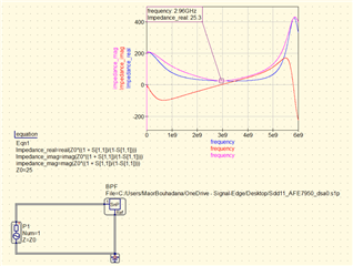
Hi, I'm willing to use the AFE from 400 - 6000MHz with the same port so I'm dealing with wideband impedance matching. I'm looking for a measurement \ documentation of the input impedance ( real and imaginary ) of each port. from the s1p you supplied in one of the folders, it seems like the input impedance is extremely varied, suggesting a narrow-band impedance matching.

can you help me figure it out so I can implement wideband matching? as well for the tx chain
  • Hi Maor,

    Our suggestion would be to first find the balun you plan to use. Then start with a quick simulation using the S parameters to give you a starting point of how the components will affect the S11 of the circuit. And then you would be able to put it in the board to start tweaking the network to optimize based on what you see from S parameter measurements and the loss of your matching circuit.

    From doing matching networks in a different product, we saw the layout parasitics will also have an impact on the performance of your matching network considerably at higher frequencies because the terminations on the RF channels are sensitive. For such a wide band match, some resistive components might also be useful in order to shrink the response in the smith chart closer to 50Ohms.

    Best,

    Camilo

  • Hi Camilo, can you give me the official sNp file of the AFE? I will try to simulate it and I will see how it goes.

  • Hi Maor,

    The S parameters for the AFE7900 are in the OneRelease inside Simulatio_Models.zip, which can be accessed by the link below:

    https://www.ti.com/secureresources/AFE79XX-HSC-DESIGN 

    Best,

    Camilo