Part Number: AFE7950
Tool/software:
Hi,
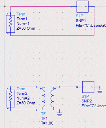
I'm working on matching the AFE7950 to a specific frequency band using the S1P file named "Sdd11_AF7950_dsa0.s1p" within a simulation tool. However, I'm unsure how to properly interpret this file and apply it to my design.
Since the ADC is differential, but the provided S-parameter file is single-port (S1P), I have a few questions:
- Should I use an ideal transformer to convert the single-ended S1P data back to differential? If so, what impedance ratio would be appropriate?
- Would it be correct to duplicate the S1P file, where each instance represents one pin of the ADC?
Any insights or guidance on the best approach would be greatly appreciated!
Thanks in advance.