This thread has been locked.

If you have a related question, please click the "Ask a related question" button in the top right corner. The newly created question will be automatically linked to this question.

LMX2824EPEVM: Full assist mode of tuning, send R0?

Part Number: LMX2824EPEVM
Other Parts Discussed in Thread: LMX2595

Tool/software:

Hi Noel,

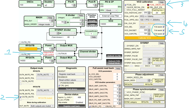
I have the full assist working in my setup.  

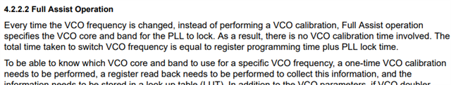
I created routine to tune across the band and record VCO_SEL, VCO_DACISET, and VCO_CAPCTRL.  I initialize with R4[14:12] asserted to force these values.

To tune, I send R5, R6, R14, R3, R1 and R8 and everything works fine.

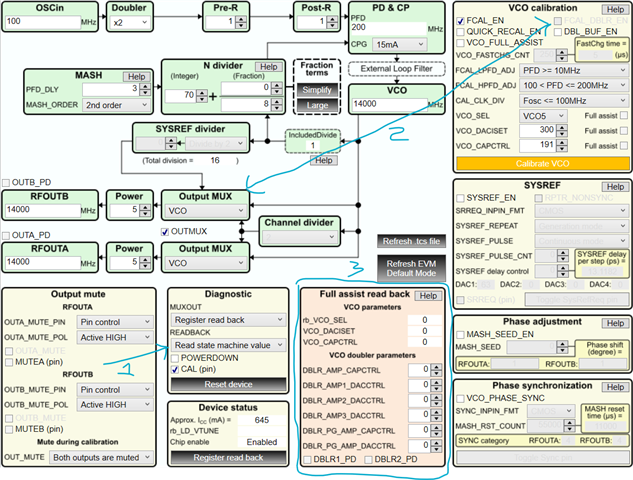
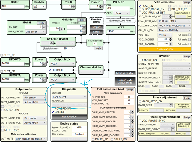
I thought I would enable double-buffering R16[8] to gain back a little on tune time, but I'm not sure what to send in R0 for full-assist mode.

I tried a couple things (i.e. disabling all the calibration), but didn't have any luck tuning.

Can double-buffering be used in full assist mode?  If so, what should I send in R0?

Thanks,
John

  • Hi John,

    did you check the example in the EVM user's guide?

    https://www.ti.com/lit/pdf/snau308

  • Hi Noel,
    Yes, I did check that but didn't see enough details.

    If I enable double-buffering, then I need to send R0 to load the registers.

    When I program R0 though things don't tune correctly.  I'm guessing I don't have the bits set correctly in R0 for full assist.

    With the LMX2595, I didn't program R0 when tuning in full assist mode.

    In my setup, I'm using a 10 MHz data rate so just looking to cut 15 us (6 registers, 2.5 us each) from the tune time.

    Thanks,
    John

  • Hi John,

    With double buffering enabled, we need to program R0 to make all the change effective. FCAL_EN should therefore be =0 otherwise there will be a VCO calibration although the calibrated data is ignored in full assist mode.

    Maybe your problem is on the VCO_FASTCHG_CNT, since your input is 10MHz, you can program this field to 50'd, CAL_CLK_DIV should be =0 to match the input frequency. 

  • Hi Noel,

    Is VCO_FASTCHG_CNT the same thing as FASTCHG_CYCLES?

    If SM cycles means State Machine cycles and these are based on OSCIN, my oscillator input is 100 MHz (my SPI is 10 MHz).

    With the default settings of FASTCHG_CYCLES=250 and SMCLK_DIV=3, I come up with 20 us [1/(100MHz/8)*250] for the fast charge ON time.

    I will experiment with these values and see if I can get double-buffering to work in full-assist.

    I did try setting all the calibration bits in R0[2,3,12,13] to 0 to disable, but was never get double-buffering to work in full-assist.

    Thanks,
    John

  • I tried messing around with those register values but could never get the combination of double-buffering and full-assist to work.

    I can make full-assist tuning work without double-buffering (R0 not sent).

    I can make no-assist tuning work with double-buffering (R0 sent).

    If you have any other thoughts on what else to try, please let me know.

    Thanks,
    John

  • Hi John,

    I assume you were using your code to program the device.

    Do you have a configuration I can use to setup TICS Pro and verify?

  • Hi Noel,

    I'm using a 100 MHz reference frequency with the reference doubler enabled to produce a 200 MHz phase detector frequency.

    I'm operating the device in fractional-n mode to produce a 25 MHz step size (denom=8).

    Below are the register values I used to initialize (after resetting the PLL).  After initialization, I send R3, R5, R6, R14, R8 and R0 to try to tune in full assist mode.

    Register Value Comment
    R0 33C8 R0[2] = 0 to disable autocal, won't tune
    R1 138B  
    R2 0F3F  
    R3 5040 Variable with tune freq (PFD_DLY)
    R4 7710  
    R5 0F2C Variable with tune freq (VCO_SEL, VCO_IDAC)
    R6 41BF Variable with tune freq (CAPCTRL)
    R7 7D40  
    R8 0046 Variable with tune freq (PLL_N)
    R9 0000  
    R10 0008  
    R11 0000  
    R12 0000  
    R13 0000  
    R14 0000 Variable with tune freq (MASH_NUM)
    R15 0000  
    R16 0101 Double-buffering enabled
    R17 1001 Ref doubler enabled, Rdiv=1 (200 MHz pfd)
    R18 0030  
    R19 01F8  
    R20 0000  
    R22 0001  
    R23 09C4  
    R30 D6D8  
    R31 0000  
    R32 026F  
    R34 00F1  
    R35 0000  
    R79 0003  

    Thanks,
    John

  • Hi John,

    I used TICS Pro default configuration and then plugged in your initialization setting, I got this.

    1. OUTMUX=0, so Output MUX is pin control. That is, whether the output is direct VCO, divide down or VCO doubler output is controlled thru pin strapping. If this is not your intention, set OUTMUX = 1. 

    2. Are you going to mute output B?

    3. If you do not need VCO doubler, FCAL_DBLR_LE should be =0. 

    4. CAL_CLK_DIV setting does not match with the reference clock frequency. This is not a big deal since you will use full assist. 

    5. Only these 3 registers will be double buffered. Other related registers such as PLL_NUM and VCO doubler parameters will not be double buffered. 

    Your initialization programs only a few registers, please program all the registers, from R79 to R0 because the application settings may not be identical to the silicon reset setting.

    I suggest use the follow configuration for LUT creation.

    1, READBACK should be =1 to read back the calibrated data.

    2. if VCO doubler is needed, set FCAL_DBLR_EN = 1

    3. read back these data

    R79	0x4F0003
    R78	0x4E0005
    R77	0x4D0005
    R76	0x4C000A
    R75	0x4B0041
    R74	0x4A0005
    R73	0x4919B9
    R72	0x481C80
    R71	0x470002
    R70	0x46FF00
    R69	0x450020
    R68	0x440004
    R67	0x430000
    R66	0x420000
    R65	0x410000
    R64	0x400022
    R63	0x3F8000
    R62	0x3E0008
    R61	0x3D0080
    R60	0x3C0000
    R59	0x3B4180
    R58	0x3A0300
    R57	0x390300
    R56	0x381FA4
    R55	0x374400
    R54	0x361E55
    R53	0x350F83
    R52	0x34C3E0
    R51	0x33318C
    R50	0x32318C
    R49	0x310C16
    R48	0x304419
    R47	0x2F0030
    R46	0x2E071A
    R45	0x2D0881
    R44	0x2C80C9
    R43	0x2BB8FC
    R42	0x2A1000
    R41	0x290EB0
    R40	0x282815
    R39	0x277802
    R38	0x260D38
    R37	0x2503E8
    R36	0x240021
    R35	0x230000
    R34	0x220000
    R33	0x210000
    R32	0x200327
    R31	0x1F0000
    R30	0x1ED6D8
    R29	0x1D0000
    R28	0x1C03E8
    R27	0x1B0000
    R26	0x1A01F4
    R25	0x190000
    R24	0x181388
    R23	0x170000
    R22	0x160001
    R21	0x150210
    R20	0x140000
    R19	0x1301F8
    R18	0x120008
    R17	0x111001
    R16	0x100001
    R15	0x0F0000
    R14	0x0E0000
    R13	0x0D0000
    R12	0x0C0000
    R11	0x0B0000
    R10	0x0A0008
    R9	0x090000
    R8	0x080046
    R7	0x077D00
    R6	0x0600BF
    R5	0x054B2C
    R4	0x040644
    R3	0x035861
    R2	0x020F2D
    R1	0x013001
    R0	0x00238C
    

    To use the LUT, first of all, initialize the device with the following configuration.

    This is again a no-assist calibration with MUXOUT set as lock detect output. The reason using no-assist calibration for initialization is to ensure the lock detector will response in full assist mode. 

    After initialization, now enable full assist mode.

    1. make change to these bits. Set FCAL_EN and FCAL_DBLR_EN = 0 first.

    2. use the data from LUT to program these registers

    3. Program R0 to make the change effective.