This thread has been locked.

If you have a related question, please click the "Ask a related question" button in the top right corner. The newly created question will be automatically linked to this question.

AFE7920EVM: phase synchronization in Rx & Tx between the 4 channels

Part Number: AFE7920EVM
Other Parts Discussed in Thread: AFE7920

Tool/software:

We use the AFE7920EVM board connected to an AMD Zynq UltraScale+ in JESD204B to perform both Rx and Tx acquisitions in the GNSS frequency range (basically, from 1160 to 2500 MHz).

We need to be phase aligned between our 4 Rx channels. Same between the 4 Tx channels.

We are OK to have a phase difference between the channels, but we need it to be constant in time and between system restarts so we can compensate it.

The Zynq configures the AFE7920 using SPI, running the CAFE library. The initial configuration was dumped using Latte running python scripts, and we now load it at start using the generated binary file.

Our setup is the following :

  • IQ sampling rate is 184.32 MHz
  • For Rx, we connect a CW generator centered on 1575 MHz with a splitter 1 -> 4 on the 4 Rx input. We receive the 4 channels in the Zynq using the JESD204B link.
  • For Tx, we generate a CW of 1 MHz in the FPGA part of Zynq on the 4 channels (data are strictly identical between the 4 channels), and we send it to the AFE using the JESD204B link. AFE is configured to transmit it at 1575 MHz.


In Rx, everything is fine, phase difference between the 4 Rx channels is constant (+/- 0.6 degrees) over time and between system restarts.


In Tx, this is not the case. Phase difference between the 4 Tx channels is constant over time, but greatly varies between system restarts, and even when stop/starting transmission without system reboot.

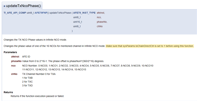
Basically, after init, we use the CAFE function updateTxNco for each of the Tx channels to set transmission frequency. This is what we do also when stop/starting transmission (we set again the same frequency).

I have the impression that the NCOs of the Tx channels do not have the same phase as they are not started simultaneously.


What shall we do to always have the same phase difference in Tx ?


Thanks & regards,

Florian.

  • Hi Florian,

    By design, the RX and TX channels of single AFE7920 are all synchronized. I will ask Mirana to help provide a few recommendations for you regarding the TX synchronization.

    -Kang

  • Hi Florian,

    Please try using the C API function, updateTxNcoPhase(). You can manually set the phase for all TX channels. Please let me know if this method provides expected results on your set up. 

    Note that "sysParams.txChainDirectCtrl" should be set to 1 before using this function. 

    Thanks!

    Mirana

  • Hello Mirana & Kang,

    thanks for your answers & support on my issue.

    Unfortunately I will not be able to test before beginning of October since our HW is currently unavailable.

    Regarding the suggested functions, I have a few questions about what it does and how it works.
    What is exactly the phase that is being set, since a signal phase changes continuously ?
    Is it set the moment the instruction is sent ?
    I need to have all 4 NCOs used for my 4 channels with the same phase, that is understood.

    But since I can not set the phase for all 4 NCOs with a single instruction, will this do the job ?
    If I set phase of NCO channel 1 to 0, then channel 2, then 3, then 4, will they be synchronous and have the same phase ?

    Also the effect of sysParams.txChainDirectCtrl = 1 is quite mysterious to me. What is it doing ? I did not find any information about it.
    It seems to be used during system initialization with Latte, so on our side, it will impact the generated SPI binary used for initialization.

    Today, it seems that this parameter is set to 0 in our script since it is the default value, so we will need to change it and redump the SPI configuration.


    Thanks for giving me answers on my questions about the NCO phase.

    Best regards,
    Florian.

  • Hi Florian, 

    1. This is a numerically controlled oscillator (NCO), so we can add phase delta to the NCOs digitally. The best way to observe the phase delta is by using a single tone waveform. 
    2. Yes, you can set the phase one NCO at a time, and they should be aligned. 
    3. The sysParams.txChainDirectCtrl function decides how the mixers in the TX digital path are configured. Because the TX path supports two mixers, front and back, there are certain functions/features that only work when using the back mixer. By setting sysParams.txChainDirectCtr equal to 1, the TX digital path is being configured to use only the back mixer. This allows us to update the NCO phase and use all configurable NCO values. 

    Thanks!

    Mirana

  • Hello Mirana,

    we are now able to test on our HW and thus we have tested the changes in our configuration that you recommend.

    Unfortunately, setting sysParams.txChainDirectCtrl = 1 returns an error in Latte :

    error_log

    I don't understand why we have this issue, our configuration is rather standard : 

    Fdac =  11 796,48 MHz

    FadcFb = 2 949,12 MHz

    DUC factor = 64

    Could you please help us ?

    Thanks & regards.

  • Hi Florian, 

    I'm checking into this and trying to replicate on my setup. Can you please provide your configuration files for me to test with? 

    Thanks!

    Mirana

  • '''
    Validation :  AFE79xx Library Version 
    				v1.67, v1.74
    Case			RX					TX						   FB						CLK					Notes
    ----	-----------------	  -----------------			-----------------			-----------			------------
    1		184.32Msps, 48410     184.32Msps, 48410			184.32Msps, 48410			FADC=2949.12M       DAC in interleaved mode
    		SerDes=7372.8Mbps     SerDes=7372.8Mbps			SerDes=7372.8Mbps			FDAC=11796.48M
    		PLL0, NCO=3500M		  PLL0, NCO=3500M			NCO=3500M                   REF=184.32M
    		
    2		245.76Msps, 24410     491.52Msps, 44210			491.52Msps, 22210			FADC=2949.12M       DAC in straight mode
    		SerDes=9830.4Mbps     SerDes=9830.4Mbps			SerDes=9830.4Mbps			FDAC=8847.36M
    		PLL0, NCO=3500M		  PLL0, NCO=3500M			NCO=3500M                   REF=491.52M
    '''
    # copied from Ti mTestSetup.py
    def FCW(Mixer, sample_Rate):
        FCW = (Mixer * (2.0 ** 32)) / sample_Rate
        return (FCW)
    def Khz_1(Mixer, sample_Rate):
        Khz = (sample_Rate * Mixer) / 2 ** 32
        return (Khz)
       
    def fconv(Mixer, sample_Rate):
        #dont do any conversion
        return Mixer
    
    sysParams.txChainDirectCtrl = 1
    sysParams.ncoFreqMode = "FCW"
    sysParams.autoFcwConvert = 1
    
    setupParams.skipFpga 				= 1
    sysParams							=	AFE.systemParams
    setupParams.fpgaRefClk 				= 184.32#122.88#
    AFE.systemStatus.loadTrims			= 1
    
    sysParams.fbEnable 					= [False]*2
    sysParams.externalClockTx			= False
    sysParams.externalClockRx			= False
    sysParams.FRef                    	= 184.32
    sysParams.FadcRx                  	= 2949.12
    sysParams.FadcFb				  	= 2949.12
    sysParams.Fdac                    	= 2949.12*3
    
    sysParams.enableDacInterleavedMode	= False 					#DAC interleave mode to save power consumption. Fs/2 - Fin spur occurs
    
    sysParams.modeTdd 					= 0		
    										# 0- Single TDD Pin for all Channels
    										# 1- Separate Control for 2T/2R/1F
    										# 2- Separate Control for 1T/1R/1F			
    
    sysParams.RRFMode 					= 0   #4T4R2F FDD mode
    sysParams.jesdSystemMode			= [3,3]
    										#SystemMode 0:	2R1F-FDD						; rx1-rx2-fb-fb
    										#SystemMode 1:	1R1F-FDD						; rx1-rx1-fb-fb
    										#SystemMode 2:	2R-FDD							; rx1-rx1-rx2-rx2
    										#SystemMode 3:	1R								; rx1-rx1-rx1-rx1
    										#SystemMode 4:	1F								; fb-fb-fb-fb
    										#SystemMode 5:	1R1F-TDD						; rx1/fb-rx1/fb-rx1/fb-rx1/fb
    										#SystemMode 8:	1R1F-TDD 1R-FDD	(FB-2Lanes)(RX1 RX2 interchanged)		; rx2/fb-rx2/fb-rx1-rx1
    
    
    sysParams.jesdLoopbackEn			= 0 #Make it 1 to Enable the JESDTX to JESDRX internal loopback
    sysParams.LMFSHdRx                	= ["48410","48410","48410","48410"]	
    										# The 2nd and 4th are valid only for jesdSystemMode values in (2,6,7,8). For other modes, select 4 converter modes for 1st and 3rd.
    sysParams.LMFSHdFb                	= ["22210","22210"]
    sysParams.LMFSHdTx                	= ["48410","48410","48410","48410"]
    sysParams.jesdTxProtocol            = [0,0]
    sysParams.jesdRxProtocol            = [0,0]
    sysParams.serdesFirmware			= True 		# If you want to lead any firmware, please speify the path here. Otherwise it will not write any firmware
    sysParams.jesdTxLaneMux				= [0,1,2,3,4,5,6,7]	
    												# Enter which lanes you want in each location. 
    												# Note that across 2T Mux is not possible in 0.5.
    												# For example, if you want to exchange the first two lines of each 2T, this should be [[1,0,2,3],[5,4,6,7]]
    sysParams.serdesTxLanePolarity		= [False]*8
    sysParams.jesdRxLaneMux				= [0,1,2,3,4,5,6,7]	#[0,1,2,3,4,5,7,6]
    												# Enter which lanes you want in each location.
    												# Note that across 2R Mux is not possible in 0.5.
    												# For example, if you want to exchange the first two lines of each 2R, this should be [[1,0,2,3],[5,4,6,7]]
    sysParams.serdesRxLanePolarity	= [False]*8
    sysParams.jesdRxRbd					= [4, 4]
    
    sysParams.rxJesdTxScr				= [True]*4
    sysParams.fbJesdTxScr				= [True]*2
    sysParams.jesdRxScr					= [True]*4
    
    sysParams.rxJesdTxK					= [32]*4
    sysParams.fbJesdTxK					= [32]*2
    sysParams.jesdRxK					= [32]*4
    
    #sysParams.ncoFreqMode 				= "1KHz"
    
    #test
    #sysParams.numTxNCO			        = 2
    
    #sysParams.txNco0					= 	[[5400,1800],		#Band0, Band1 for TxA for NCO0
    #										[500,1800],        #Band0, Band1 for TxB for NCO0
    #										[2500,1800],        #Band0, Band1 for TxC for NCO0
    #										[1800,1800]]        #Band0, Band1 for TxD for NCO0
    #
    #sysParams.rxNco0					= 	[[5400,1800],		#Band0, Band1 for RxA for NCO0
    #										[500,1800],        #Band0, Band1 for RxB for NCO0
    #										[2500,1800],        #Band0, Band1 for RxC for NCO0
    #										[1800,1800]]        #Band0, Band1 for RxD for NCO0
    #
    #sysParams.fbNco0					= 	[1800,1800]			#FBA, FBC for NCO0
    #sysParams.fbNco1					= 	[1800,1800]			#FBA, FBC for NCO1
    #sysParams.fbNco2					= 	[1800,1800]			#FBA, FBC for NCO2
    #sysParams.fbNco3					= 	[1800,1800]			#FBA, FBC for NCO3
    
    sysParams.txNco0					= 	[[fconv(2600, sysParams.Fdac),fconv(1800, sysParams.Fdac)],		#Band0, Band1 for TxA for NCO0
    										[fconv(2600, sysParams.Fdac),fconv(1800, sysParams.Fdac)],        #Band0, Band1 for TxB for NCO0
    										[fconv(2600, sysParams.Fdac),fconv(1800, sysParams.Fdac)],        #Band0, Band1 for TxC for NCO0
    										[fconv(2600, sysParams.Fdac),fconv(1800, sysParams.Fdac)]]        #Band0, Band1 for TxD for NCO0
    
    sysParams.rxNco0					= 	[[fconv(2600, sysParams.FadcRx),fconv(1800, sysParams.FadcRx)],		#Band0, Band1 for RxA for NCO0
    										[fconv(2600, sysParams.FadcRx),fconv(1800, sysParams.FadcRx)],        #Band0, Band1 for RxB for NCO0
    										[fconv(2600, sysParams.FadcRx),fconv(1800, sysParams.FadcRx)],        #Band0, Band1 for RxC for NCO0
    										[fconv(2600, sysParams.FadcRx),fconv(1800, sysParams.FadcRx)]]        #Band0, Band1 for RxD for NCO0
    #test
    #sysParams.txNco1					= 	[[fconv(2600, sysParams.Fdac),fconv(1800, sysParams.Fdac)],		#Band0, Band1 for TxA for NCO0
    #										[fconv(2600, sysParams.Fdac),fconv(1800, sysParams.Fdac)],        #Band0, Band1 for TxB for NCO0
    #										[fconv(2600, sysParams.Fdac),fconv(1800, sysParams.Fdac)],        #Band0, Band1 for TxC for NCO0
    #										[fconv(2600, sysParams.Fdac),fconv(1800, sysParams.Fdac)]]        #Band0, Band1 for TxD for NCO0
    
    sysParams.fbNco0					= 	[fconv(2600, sysParams.FadcFb),fconv(1800, sysParams.FadcFb)]			#FBA, FBC for NCO0
    sysParams.fbNco1					= 	[fconv(2600, sysParams.FadcFb),fconv(1800, sysParams.FadcFb)]			#FBA, FBC for NCO1
    sysParams.fbNco2					= 	[fconv(2600, sysParams.FadcFb),fconv(1800, sysParams.FadcFb)]			#FBA, FBC for NCO2
    sysParams.fbNco3					= 	[fconv(2600, sysParams.FadcFb),fconv(1800, sysParams.FadcFb)]			#FBA, FBC for NCO3
    
    sysParams.numBandsRx				= [0]*4					# 0 for single, 1 for dual
    sysParams.numBandsFb				= [0,0]				
    sysParams.numBandsTx				= [0,0,0,0]
    
    sysParams.ddcFactorRx             	= [16]*4			# DDC decimation factor for RX A, B, C and D
    sysParams.ddcFactorFb             	= [16]*4
    sysParams.ducFactorTx             	= [48]*4
    
    
    ## The following parameters sets up the LMK04828 clocking schemes
    lmkParams.pllEn						=	True#False
    lmkParams.inputClk					=	1474.56#737.28
    #The External Sysref Frequency should be an integer factor of: 1.92MHz
    #The period of the SYSREF must be equal to or an integral multiple of the period of the multi-frame in 8b/10b mode (K=32) -> 184.32/32 = 5.76MHz
    #this value is useless as it is overwritten at the end of the script
    lmkParams.sysrefFreq				=	2949.12/1024
    lmkParams.lmkFrefClk				=	True
    
    ## The following parameters sets up the register and macro dumps
    logDumpInst.setFileName(ASTERIX_DIR+DEVICES_DIR+r"\Afe79xxPg1.txt")
    logDumpInst.logFormat				= 0x20FF
    logDumpInst.rewriteFile				= 1
    logDumpInst.rewriteFileFormat4		= 1
    device.optimizeWrites				= 0
    device.rawWriteLogEn				= 1
    
    
    ## The following parameters sets up the SYNCIN and SYNCOUT to interface with the TSW14J57
    sysParams.jesdABLvdsSync			= 0
    sysParams.jesdCDLvdsSync			= 0
    sysParams.rxJesdTxSyncMux			= [0,0,0,0]
    sysParams.fbJesdTxSyncMux			= [0,0]
    sysParams.jesdRxSyncMux				= [0,0,0,0]		#[0,0,1,1]
    sysParams.syncLoopBack				= True
    
    # ## The following parameters sets up the AGC
    # sysParams.agcParams[0].agcMode = 1 ##internal AGC
    # sysParams.agcParams[0].gpioRstEnable = 0 ##disable GPIO based reset to AGC detector 
    # sysParams.agcParams[0].atken = [0, 1, 0] ##enable big and small step attack
    # sysParams.agcParams[0].decayen = [0,1,0] ##enable big and small step decay
    # sysParams.agcParams[0].atksize = [2,1,0] ## bigs step = 2dB, small step = 1dB
    # sysParams.agcParams[0].decaysize = [2,1,0] ##big step = 2dB, small step = 1dB
    # sysParams.agcParams[0].atkthreshold = [-1, -2, -14] ##attack threshold
    # sysParams.agcParams[0].decaythreshold = [-14, -6, -20] ##decay threshold
    # sysParams.agcParams[0].atkwinlength = [170, 170] ## detector time constant expressed inn absolute time in ns. 
    # sysParams.agcParams[0].decaywinlength = 87380 ##detector time constant expressed in absolute time in ns. All detectors use the same value for decay time constant
    # sysParams.agcParams[0].atkNumHitsAbs = [8,8] ##absolute number of times signal crosses threshold. These crossing are with respect to the FADC/8 clock
    # sysParams.agcParams[0].decayNumHitsAbs = [100,100] ##absolute number of times signal crosses threshold. These crossing are with respect to the FADC/8 clock
    # sysParams.agcParams[0].minDsaAttn = 0 ##minimum DSA attenuation used by AGC
    # sysParams.agcParams[0].maxDsaAttn = 22 ##maximum DSA attenuation used by AGC
    # sysParams.agcParams[0].totalGainRange = 22 ##total gain range used by ALC for gain compensation
    # sysParams.agcParams[0].minAttnAlc = 0 ##minimum attenuation used by ALC for compensation when useMinAttnAgc = 0
    # sysParams.agcParams[0].useMinAttnAgc = 1 ##enable ALC to use minimum attenuation from AGC for which compensation is required.
    # sysParams.agcParams[0].alcEn = 1
    # sysParams.agcParams[0].alcMode = 0 ##floating point DGC
    # sysParams.agcParams[0].fltPtMode = 0 ##if exponent > 0, dont send MSB
    # sysParams.agcParams[0].fltPtFmt = 1 ##3 bit exponent
    
    
    ## The following parameters sets up the GPIOs
    sysParams.gpioMapping={
    		'H8': 'ADC_SYNC0',
    		'H7': 'DAC_SYNC0',
    		'N8': 'ADC_SYNC2',
    		'N7': 'ADC_SYNC3',
    		'H9': 'ADC_SYNC1',
    		'G9': 'DAC_SYNC1',
    		'N9': 'DAC_SYNC2',
    		'P9': 'DAC_SYNC3',
    		'P14': 'GLOBAL_PDN',
    		'K14': 'FBABTDD',
    		'R6': 'FBCDTDD',
    		'H15': ['TXATDD','TXBTDD'],
    		'V5': ['TXCTDD','TXDTDD'],
    		'E7': ['RXATDD','RXBTDD'],
    		'R15': ['RXCTDD','RXDTDD']}
    		
    #AFE.systemParams.papParams[0]['enable'] = True
    #AFE.systemParams.papParams[1]['enable'] = True
    #AFE.systemParams.papParams[2]['enable'] = True
    #AFE.systemParams.papParams[3]['enable'] = True
    setupParams.skipLmk	=	False
    
    #AFE.systemParams.txChainDirectCtrl = 1
    AFE.initializeConfig()
    lmkParams.sysrefFreq = AFE.systemStatus.sysrefFreq
    lmkParams.lmkPulseSysrefMode = False
    
    lmklogDumpInst=mLogDump.logDump(ASTERIX_DIR+DEVICES_DIR+r"\Afe79xxPg1_LMK.txt")
    lmklogDumpInst.logFormat=0x1
    lmk.logClassInst = lmklogDumpInst
    lmk.rawWriteLogEn=1
    
    AFE.LMK.lmkConfig()

    Hello Mirana, here is our script. By changing the Tx DAC frequency to 8 847,36MHz, the configuration is accepted. But we are not sure about the use of FCW.

  • And could you also advice which function shall we use to update Tx frequency ?

    updateTxNcoMultiNcoMode() or updateTxNco() ?

    For the moment, we use updateTxNco(), but it does not seem to work (on the bench the Tx spectrum on the spectrum analyzer has 2 peaks at frequencies that do not correspond to the set one). We have noticed that in Latte script, function updateTxNcoMultiNcoMode() is used.

    We use latte 2p8 and CAFE 2p6.

    Thanks.

  • Hi Florian, 

    The updateTxNcoPhase() function only works for Fdac rates equal to or less than 9G. For a 9G Fdac rate, the DAC also cannot be in IL mode.  

    Because you're using a single band configuration, the updateTxNco() function should be sufficient. However, I'm seeing similar behavior on my setup after using the updateTxNco() function. It looks like the updateTxNco() function works as expected when the txDirectChainCtrl parameter is set to 0. I am working to test the register writes to update the NCO phase, without that parameter. I will update you as soon as I am able; I appreciate your patience!

    Thanks!

    Mirana

  • Hello Mirana,

    thanks for taking time to help us.

    Actually, the phase stability is achieved by setting  txDirectChainCtrl=1, so we do not need to use updateTxNcoPhase(). 

    We have set Fdac =  8 847,36MHz and use updateTxNcoMultiNcoMode() and updateRxNcoMultiNcoMode() to change frequency, and the phase difference is now constant between start/stop and system reboots. We have also tested the TDD override with success.

    With this setup, we have achieved what we needed regarding phase stability.

    The remaining issue on our side is to change Nyquist zone dynamically as described here :  AFE7920EVM: How to use the opcodes to update system after initial configuration 

    Thanks,

    Florian.