This thread has been locked.

If you have a related question, please click the "Ask a related question" button in the top right corner. The newly created question will be automatically linked to this question.

CC1190: RF Antenna tuning

Part Number: CC1190
Other Parts Discussed in Thread: LAUNCHXL-CC13-90EU

Tool/software:

Hi Team,

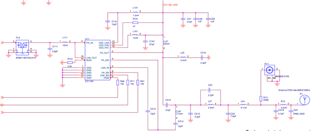
Currently we are working on the RF Tuning for 868MHz in this circuit where can I place the 50ohm SMA?

Because in the development kit till the L24 in the shielded but in the CC1190 datasheet followed components  C212, L27,C25 and L24 mentioned has Part of antenna match. 

in the spectrum analyzer if I use Capacitor as series (after L24 component) it will drop the power from 24dBm to 18dBm so is there any solution on that?  if yes same as inductor is there any cons? 

 Looking for the reply.

Thanks

  • Hi,

    Please clarify your measurements: if you mount a capacitor at R13 are you also removing the Pi filter components C218 and R12?

    Have you compared to a LAUNCHXL-CC13-90EU design for a comparison?

    Regards,

    Zack

  • 1) We mounted a Cap in the R12 (2.5pF) and C23 (1.2pF) and the smith chart value is attached below. in this case we checked in the spectrum analyzer and it will drop the power from 24dBm to 18dBm. but if I install 0ohms in the R12 power came back to 24dBm.

    2) Yes we compared and design same as the LAUNCHXL-CC13-90EU.

    Looking for your valuable reply.


    .

  • Hi,

    If measuring the conducted performance then C218 and R12 must be DNM, otherwise the desired impedance matching will be altered and will result in undesired performance.

    R13, the 0R resisitor to the JSC or SMA 50 Ohms connector (depending on what you will use), is then mounted.

    Regards,

    Zack