This thread has been locked.

If you have a related question, please click the "Ask a related question" button in the top right corner. The newly created question will be automatically linked to this question.

TMS570LC4357: SPI3_Communication Issue

Part Number: TMS570LC4357

We are using SPI3 communication to interface with the IC 25LC320. We are able to read the status register and also send data. The transmission is exactly as specified in the datasheet.

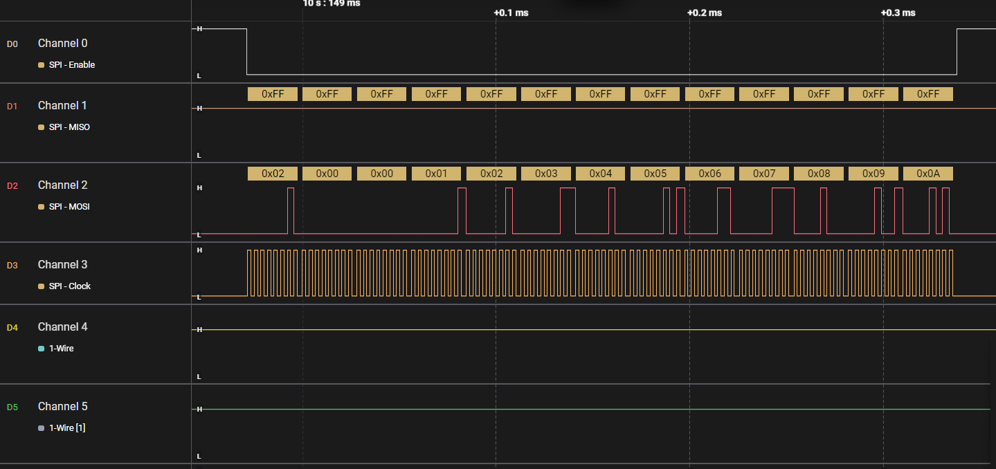
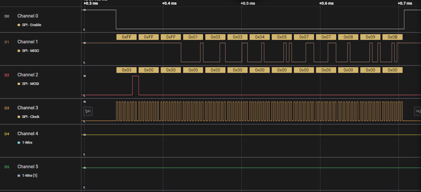
However, while reading, the last bit is missing and is read as high. I have attached both the write operation and read operation images for reference.

Please help me resolve this issue.ReadOperation.pngWriteOperation.png


  • Hi Prasanna,

    Could you please try below suggestions once:

    1. Clock Polarity/Phase Configuration

    • Check if your SPI mode (CPOL/CPHA) matches the 25LC320 requirements
    • The 25LC320 typically operates in SPI Mode 0 (CPOL=0, CPHA=0)

    2. Timing Issues

    • The last bit may be getting cut off if the CS (chip select) signal is deasserted too early
    • Ensure proper hold time after the last clock edge before deasserting CS

    You can also increase transmit end to chip select inactive time, try increasing this parameter as well once:

    3. Hardware Configuration

    • Verify pull-up/pull-down resistors on the MISO line
    • Check for signal integrity issues (noise, reflections)
    • Ensure proper termination of SPI lines

    4. Software Configuration

    • Review your SPI frame configuration (data length settings)
    • Check if there's an off-by-one error in your read routine

    --

    Thanks & regards,
    Jagadish.

  • We have implemented all the configuration changes as suggested. However, the communication was still not working initially.

    Later, we changed the SPI mode from Mode 0 to Mode 1, after which the data is being received correctly from the EEPROM.


  • Hi Prasanna,

    Later, we changed the SPI mode from Mode 0 to Mode 1, after which the data is being received correctly from the EEPROM.

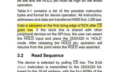
    According to 25LC320 datasheet, they didn't mention the mode explicitly. But i found this information:

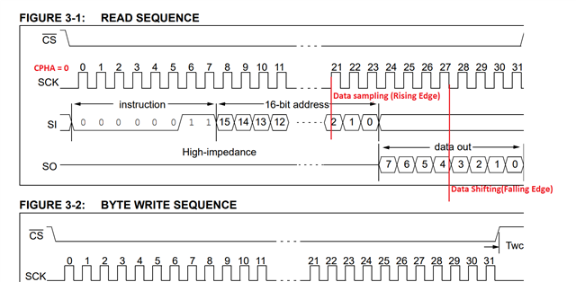
    From this i understood that, 25LC320 data sampling is on Rising edge and data shifting is on Falling edge,

    So as per this TMS570 controller should latch or sample its data on Rising edge as 25LC320 is shifting data is on falling edge:

    As you can see in Mode-1 this is matching with 25LC320, so Mode-1 should be correct as per my understanding as well.

    --

    Thanks & regards,
    Jagadish.