This thread has been locked.

If you have a related question, please click the "Ask a related question" button in the top right corner. The newly created question will be automatically linked to this question.

TRF371109 I/Q mapping issues

Other Parts Discussed in Thread: TRF371109

My customer is having a problem with the TRF371109.  Essentially he’s using the two parts shown in the diagram below on two different eval boards.  If he cycles power on either one, the mapping of his (I,Q) gets out of whack.  When he expects (I,Q), he sometimes gets any combination of (-I,Q), (I,-Q), (Q,I), (-Q,I) … etc.  The values are exactly correct when compared to the ADF4350 LO signal’s IQ, but seem to be mapped internally incorrectly.  Once he synchs them up (by cycling power some more), he can get the correct output and it will stay that way.  He’s removed the ADF4350 and used a second signal generator with the same results .   

 0675.diagram.doc

Can you comment on the issue he is seeing?

  • Hi Todd,

    I addressed a similar issue a little while back on here on e2e after carrying out a test similar to what you described. In place of the ADF4350, I used a signal generatior, but It so happened that I didn't see the TRF371109 behaving as described. Find below my findings:

    I ran a test similar to what you described using a TRF371109 EVM.

    5V supply to J11, J12 grounded,frequency allocation band set to 900M,  F_LO = 900 MHz  at 0 dBm, BB =300 KHz, F_RF signal= 900  Mhz +300 KHz at -40 dBm.

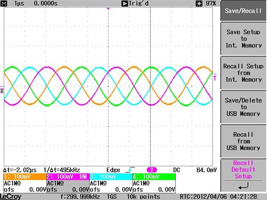
    To be able to view I, I_bar, Q, Q_bar on an oscilloscope, shunts w5 -w7 were taken off and SMA connectors J2, J4, J8, J13 were connected to the scope. The BB gain on the 3711 gui was set to 20.

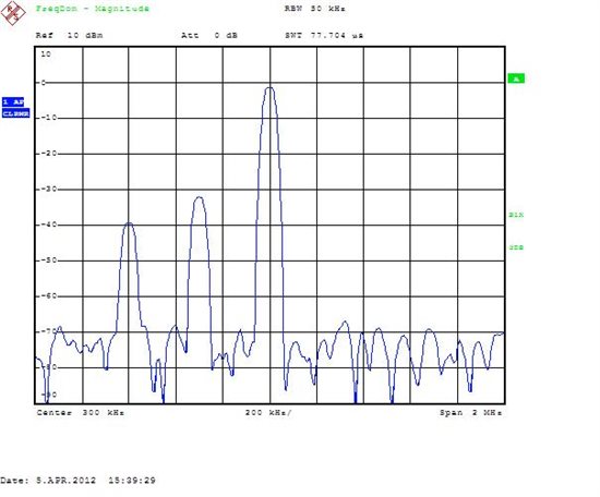
    The LO signal generator was switched on and off but the behaviour you described in the thread was not observed. The IQ baseband signals weren't observed to move around as they stayed in the same place. See attached scope shot. In the frequency domain ( a spectrum analyzer having differential input ports was used), the signals stayed at the same placed  and didn't get flipped when the LO signal generator was turned on and off. In the second scope shot (frequency domain), you can see the negative image of the baseband signal.

    Thanks

    Onyx