This thread has been locked.

If you have a related question, please click the "Ask a related question" button in the top right corner. The newly created question will be automatically linked to this question.

TRF3765 EVM

Other Parts Discussed in Thread: TRF3765, TRF3765EVM, CLOCKDESIGNTOOL

We are testing the TRF3765 EVM and we have  some questions about it:

1- We select the file TRF3765.FracMode.3p3Vtank.2600MHz.txt (mentioned at user guide) and set the registers, we can see the carrier at 2600Mhz but it only has -27 db is it ok? Can we have more power (db) at the output?

 2- We need at the output a carrier at 437MHz we know that we have to change the register configuration but is necessary to change the component of the loop filter?

3- Can we also change the oscillator of the board or you do not recommend this?

4- The last one, do you know the BW and phase of the filter that the EVM has?

Thank you for your help.

 Best regards, Mariana.

  • A power of -27dBm may indicate that measurement equipment is connected to an output buffer that is powered down. The configuration file mentioned only powers on one of the output buffers. -27Bm is not normal. Normal power levels can be seen in datasheet figure 59.

    With the LO output running at 437MHz, the VCO will operate at 8 * 437MHz = 3496MHz. This is close to the frequency for which the loop filter is optimized. It is generally only necessary to redesign the loop filter when changing the pfd frequency, particularly when decreasing the pfd frequency by an octave or more.

    The oscillator footprint is intended to accomodate a range of oscillators on the market. You can also connect an external input any bypass the on-board oscillator for testing without any soldering.

    The Loop Filter Calculator Tool available on the TRF3765 page allows the user to enter loop filter values and calculate the open and closed loop responses.

  • Peter,

    According with your answer we can set at the GUI software Fref=61.44MHz, Step Size=30.72MHz and Fout=3496MHz and see a 437Mhz carrier at the LO4 output which divided by 8 .

    And is not necessary do changes at the loop filter.

    That is right?

    Our Loop Filter Calculator Tool do not work fine can you tell us the  BW and phase of the filter that the EVM has?

    Thank you.

    Mariana

  • Peter,


    We also need to know if the TFR3765 supports a loop filter with a BW of 1MHz, we have implemeted this but it did not work.

    Can the PLL lock ok with this filter?


    Thank you.

    Mariana.

  • As the ratio of pfd frequency / loop BW becomes smaller, the PLL becomes less stable. An analytic solution is somewhat complex, but a rule of thumb is to stay away from the absolute maximum of pfd / BW > 10.

    In this particular instance, the capacitive values of the loop filter become so small that the system will be quite poorly conditioned. The calculator tool calls for <0.25pF on C1 and even smaller on C3, compared to 160kohm resistors. Parasitics will easily dominate performance and cause peaking in the closed loop response.

    To explore the absolute maximum achievable loop filter bandwidth, you will need to use integer mode. The noise characteristic of a fractional modulator is high-pass, and an extremely wide bandwidth would pass t hrough all of the fractional modulator noise. You might also fit a shield over the TRF3765 EVM shield landing area.

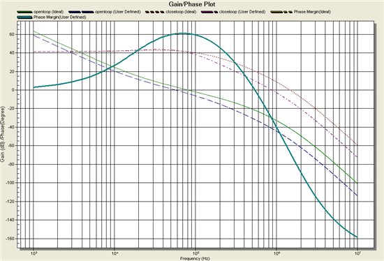
    The gain and phase plots of the 30.72MHz pfd loop filter are attached below as the user-defined curves. (2200pF, 22000pF, 475ohms, 220pF, 475ohms, 220pF, 475ohms)

  • Peter,

    We set at the Loop Filter Calculation the following parameters:

    BW=1KHz

    Phase Margen=48°

    Fref=20MHz

    Fout=437MHz

    R=20

    Kvco=65MHz/V

    Icp=2mA

    And we obtain the following values:

    C1=2,2uF

    R2=21Ohm

    C2=21,1uF

    R3=21Ohm

    C3=0,56uF

    R4=0

    C4=0

    Is correct the result of the software or our Loop Filter Calculator works bad?

    We need a Loop filter of 1KHs because we want to do an audio  FM modulator with this PLL.

    In your opinion is it not possible use a loop filter with this BW (1KHz) if we use a Fpfd= 30.72MHz or a Fpfd= 1MHz ?

    Thank you for your help.

    Mariana.

  • 1kHz loop filter BW is quite possible. Earlier in the thread the need was stated as 1MHz loop filter BW, which is not quite so feasible.

  • Peter,

    Thank you for yor answer.

    In your last answer you mentioned that is possible use a loop filter with a BW of 1KHz so we have calculated the componentent of the filter with the Loop Filter Calculator, Can you tell us if it is ok becuase this software does not work fine at our PC?

    We set:

    BW=1KHz

    Phase Margen=48°

    Fref=20MHz

    Fout=437MHz

    R=20

    Kvco=65MHz/V

    Icp=2mA

    And we obtain the following values:

    C1=2,2uF

    R2=21Ohm

    C2=21,1uF

    R3=21Ohm

    C3=0,56uF

    R4=0

    C4=0

    If we change the loop filter components of the TRF3765EVM will it work without problems?

    We already have implement a board like the EVM with the loop component mentioned before but it does not work, we want to dismiss a loop filter problem.

    Also we already have a poor power dbm at the output and we have power on the corresponding  output buffer is there any other register to change that help us to have a higher power?

    Thank you for you help.

    Mariana. 

  • The VCO is operating at 437MHz * 8 = 3496MHz. This is the frequency that must be plugged into the Loop Filter Calculator Tool.

    This yields a filter of 0.22uF, 169ohms, 2.2uF, 169ohms, 47nF, after rounding to standardized values. This filter does stabilize when using a 1MHz PFD frequency and a 1kHz BW along with the desired parameters.

    The measured power from a default EVM under the noted conditions and loop filter is 1.5dBm. A power of -27dBm indicates that the VCO may be locked but you are only measuring leakage. Check that
    - there is a pull-up to a powered node on the output,
    - the output buffer is turned on
    - the output is not loaded with an accidental short.

  • Dear Peter,

    Please can you do another calculation with the Loo Filter Calculator Tool (this software does not work fine at our PC) with the next parameters and send us an screen print:

    BW=1KHz

    Phase Margen=48°

    Fref=61MHz

    Fout=3496MHz

    R=61

    Kvco=65MHz/V

    Icp=2mA

    Thank you for your help,

    Mariana. 


  • Mariana,


    Do you have MathCAD on your PC?  Dean Banerjee (was at National now TI) wrote MathCAD files to compute loop filter values and then plot the response.  I have copies of  some of his MathCAD files.

     If not, Analog Devices also has a nice PLL program you could use called ADISIMPLL -- maybe that works on your PC.  :)

    Eric Hooker

    RF Consultant

  • Eric,

    Can you send us the MathCAD files you have?

    Thank you.

  • There are no previously-known problems reported on Windows XP or Windows 7. If there are problems with the software, TI would like to resolve any issues.

    There are many loop design tools available, including another free tool offering from ti at http://www.ti.com/tool/clockdesigntool.

  • 1184.PLLdes_T25.mcd

    Mariana, 

    Attached is a Dean Banerjee MathCAD file for PLL design and simulation.  The attached file is configured for a PLL (VHF 2-way radio band) I did in the past.  The user must  enter data at various places within the file starting at the top of page 1.  I have used Dean's MathCAD sheet successfully for many PLL designs.  I would usually simulate the PLL with additional tools such as Agilent ADS before bread-boarding and testing the design.

    Contact me if you need detailed assistance with your designs.  My LinkedIn page is listed below.

    Regards,

    Eric Hooker

    RF Consultant

    http://www.linkedin.com/in/erichookerrfconsultant

  • Dear Pete,

    I'm facing a similar issue with the loop_filter_calculator program.

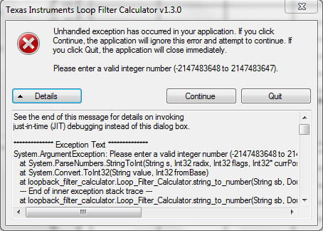
    After pressing Calc and Plot button, right after first execution I get the following error.

    I tried on 3 different OS:

    1. WinXP 32bit
    2. Win7  32bit
    3. Win7 64bit
    The error I get is the same in all the reported platforms.
    I hope it will be fixed soon.
    Thanks
    Kind regards,
    Alberto
  • It appears that as the BW approaches 1kHz, the calculations approach a singularity which exceeds the software's numeric representations. The capacitor values become physically unrealizable, either huge or even negative. 1kHz is about two orders of magnitude away from prior BW design targets.

    http://www.ti.com/tool/clockdesigntool offers an alternative calculation tool.

    TI appreciates the screen shot of the error report. Very helpful.

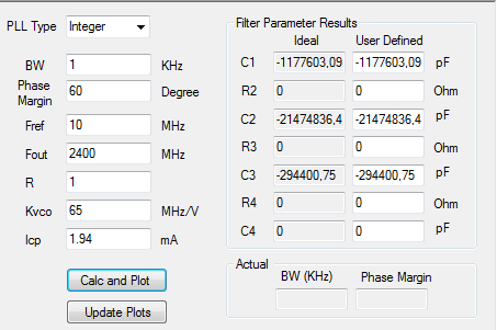
  • Dear Pete, the error reported in the previous screenshot refers to the following default loop filter configuration

    Even changing design input values the error shows up at anytime after pressing the calc or update buttons.

    Hope it will help.

    Regards,

    Alberto

  • The loop filter calculator tool doesn't work for me as well:

    I'd like to design a loop filter for the TRF3765 using a 10 MHz reference but I get the error which has already been reported earlier in this thread and the calculated values for the Rs and Cs are nonsense.

    The National Clock Design Tool doesn't seem to be suitable for my task.

    Can you recommend another tool? Or give hints on how to perform the calculation manually?

    Kind Regards,

    Max

  • Max,


    You are correct in discovering that the loop filter calculator tool does not support your requirements and displays an error message with unrealizable resistor and capacitor values.  The limiting factor in your requirements is the low bandwidth of 1kHz.  Decreasing the bandwidth size below 3kHz causes the loop filter calculator tool to begin displaying unrealizable resistor and capacitor values and using these low bandwidths will cause parasitics in the system.


    Adam    

  • Adam,

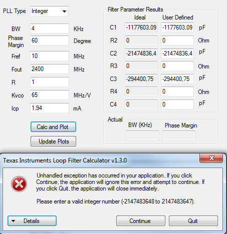
    Increasing the bandwidth to 4 kHz does unfortunately not change the situation:

    For a bandwidth >= 1000 kHz (bandwidth is not really a crucial requirement for my appilcation) the calculated values become more reasonable but the programm continues to throw an execption anyway.

    For this reason I don't feel comfortable relying on the calculated values.

    Best regards

    Max

  • Max,


    I input your requirements into the windows 7 version of the loop filter tool v1.3.0 on my windows 7 machine and obtained the screen shot below.  If you are still receiving the error message when you are inputting valid bandwidths, try restarting the program. 


    Adam

  • Adam,

    Thanks for providing your results.

    Just for your information: Entering exactly the same values I end up getting the error I have already posted. I used v1.3 on two different Win7 x64 machines and restarted the tool.

    Best Regards,

    Max

  • Dear Max,

    I notice same issue with a french windows XP version. I tried to change "regional and language option" to "english(US)".

    Now, it seems to work.

    Best regards.

    Don.

  • Dear Don,

    I can confirm that changing the region and language settings to "English  (US)" prevents the tool from crashing!

    Thank you very much for this hint.

    Best Regards,

    Max

    PS: I'm using a German Windows 7 x64 installation