Because of the holidays, TI E2E™ design support forum responses will be delayed from Dec. 25 through Jan. 2. Thank you for your patience.

This thread has been locked.

If you have a related question, please click the "Ask a related question" button in the top right corner. The newly created question will be automatically linked to this question.

LMX2581 Frequency Synthesizer IC does not output correct frequencies.

Other Parts Discussed in Thread: LMX2581, CODELOADER

I am prototyping a frequency synthesizer circuit with the LMX2581 Frequency Synthesizer IC. 

 Sometimes the IC generates the correct frequency, sometimes it does not.


In particular, when sending commands to the IC, it does not seem to be possible to set the OUTB_MUX and OUTA_MUX bits in Register #5 in order to bypass the VCO divider.   On some of the higher frequencies (>1880 MHz), it appears that the desired frequency is always divided by two.

When trying to set the other high frequencies the IC usually outputs a low frequency around 904 MHz.

I'm on version D of the datasheet which apparently corrects some mistakes in version C of the datasheet.

  • Thomas,

    We have tested this functionality thoroughly and never seen such an issue.  If you post the registers and the OSCin frequency for what you are trying to get for the non-divided frequency, I can analyze this and see if there are any issues.


    Regards,

    Dean

  • Hi Dean,

          Thanks.

    I'm using a  10 MHz Reference clock ( OSCin ) with a Reference divider ratio (PLL_R)  =10.

    So my phase detector frequency is 1 MHz.

    //**********************    When trying to set a frequency of 2400 MHz for example these are my values:    **************************************//

    The measured output frequency is:      1200.007 MHz.

    PLL_N = 2400       (2400 x 1 MHz = 2400 MHz)

     PLL_NUM = 0     

     PLL_DEN = 1,000,000   (since the requested output frequency is a whole multiple of 1 MHz, the fractional part of the divider isn't beingused for this specific frequency).

    The Register Values that I set  are:

    R[15]= 21FE80F

    R[13]= 4082C10D

    R[10]= 210050CA

    R[9]= 3C7C039

    R[8]= 207DDBF8

    R[7]= 1022237

    R[6]= 406

    R[5]= 8005

    R[4]= 40F804

    R[3]= 2001E7A3

    R[2]= CF42402

    R[1]= C00020A1

    R[0]= 69600000

  • Hi Dean,

              It's Monday July 1.  Have you found any clues as to why I can't get the

    LMX2581 to produce the right frequency?

    Tom

  • Thomas,

    I looked at the file and see nothing suspiciuos.  We do recommend a different programming sequence, but this would not cause what you are seeing.

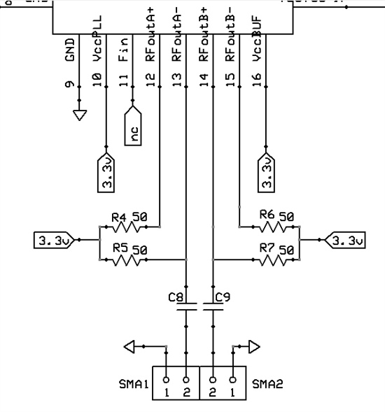
    Do you have the unused side terminated with 50 ohm (AC coupled)?   If not, this can make some high harmonics and maybe this is what you are picking up on.

    Also, have you compared the power level for the unwanted divide by 2 to the intended signal?


    Regards,

    Dean

  • Hi Dean,

                           I'm not sure what you mean by "unused side" since there are 2 outputs both of which are differential.

    I'm only using OutputA for now.  OutputB is turned off in software.  Even after contacting the  TI Tech support phone

    number it wasn't clear to me exactly how the outputs are supposed to be connected in order to use them single-ended.

    Here's the output portion of the circuit as it stands now:

    The unwanted divide by 2 signal is everything and it's strong  ( I don't remember the exact power level off the top of my head).

    There is no intended signal.

    *****

    I tried a couple of things:

    1. Disconnecting the FASTlock output resistor.

    2. A different loop filter.

    Neither of these modifications changed anything.

    ++Tom.

  • Hi Dean,

                        So how can I get a resolution to this problem?  I've got a good bit of time, effort and

    money invested in developing this and I still don't have a working product.  I examined the datasheet

    very closely several times before I even began this project. But of course I could still be missing

    something. 


    ++Tom.

  • Thomas,

    I used codeloader that does program these registers in a different order as recommended by our datasheet and our CodeLoader software off the web.  The main difference is it first programs register R5 with the reset bit to reset all registers, including those not disclosed to the user. These are reset upon power on reset, but if you write bad data to these regsiters (like R14), it will put bad data to our device.  This is not typical, but sometimes when the CLK and DATA lines are shared, this can happen.  Also, I note that you have the BUFFEN_DIS bit disabled.  This means that you have to have the BUFFEN pin pulled high or else the output buffer will be off, but the PLL will be locked. 

    I suspect one of the following:

    1.  You are writing erroneous data to hidden regsiters and not resetting the part.  Solution is to reset with the R5 programming at the beginning as the datasheet suggests.  Mainly a concern if you are sharing CLK and DATA lines with another device.  Solution -->  Program R5 first with reset as the datasheet recommends.

    2.  Your test equipment is not showing you the full picture.  For instance the E5052 phase noise analyzer gives the wrong frequency if the harmonics are very high.  Because your termination is asymmetric, I suspect that the harmonics will be high.   Solution to this would be to use a spectrum analyzer or use the E5052 in spectrum analyzer mode.  I am confident that when you see 1/2 the signal, there is a second harmomic (intended signal) of some level.

    3.  Your output power is very low because BUFFEN_DIS =0 and BUFFEN pin is low.  Solution ->  Set BUFFEN_DIS=1 if any suspicion.

    4.  Programming speed issue.   You are not following the wait times in the datasheet and the capacitors are not charging up and there is improper VCO calibration.

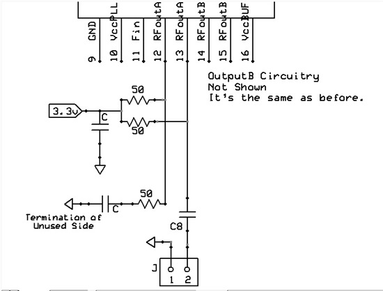
    The termination you have is asymmetric because one side is loaded with 50 ohm test equipment and the other side is not.  Ideally, it would be best to put a cap and 51 ohm resistor to the unused side of RFoutA.

    Also, we need to be sure if this is an issue of the divide by 2 not working or something else.  The VCO divider is after the PLL, so if you program the lock detect pin, then you can check the PLL to see if it says it is locked.  If it's just a divider issue, the PLL should say it's locked, but the output would be off.  But it makes no sense why the divider would be doing anything if divided and we have never seen this. 

    Regards,

    Dean

  • Hi Dean,   

            I'm still not having success with the LMX2581.

            I checked the firmware code that loads the registers. It was loading the registers in the correct sequence with 2 exceptions:

    1. It was not loading Register 5 [R5] with the reset bit upon power-on.

    2. It was not setting the VCO_DIV value to 6 before setting it to 4.


    ACTION:

              I changed the firmware so that the program would do those two things. As far as I can determine, it's loading everything in the recommended order .But I'm still not seeing any improvement.

    By the way, the previous listing that showed the values which were loaded into the registers, was not in the order in which the registers were loaded. It was simply a numerical sequence starting at R13 going to R0.

    FOLLOWUP:  

              I'm attaching some measurements that I made. Hopefully that will give you some insight as to what I'm doing wrong. I used pins 25\LD and 30\MuxOut to access the digital Lock Detect and analog ( Vtune ) Lock Detect Signals which I included in the measurements. Unfortunately this about the most information that I can give you right now.  I'm now unemployed so I don't have access to any sophisticated lab instruments. A frequency counter and a power meter are all I have now.

    ***

    By the way, ver D of the specsheet refers to VCO_DIV in two ways: Most of the time VCO_DIV refers to the Output Divide Ratio. However on page 22 when talking about the field in R3, VCO_DIV[4:0], where the Output Divide Ratio is set, VCO_DIV is used to refer to value placed in the register field: which appears to be                            (OUTPUT_DIVIDE_RATIO/2)-1 .

     This leaves me wondering:  When following the "set to 6, before setting to 4" rule, is that referring to the OUTPUT_DIVIDE_RATIO=4  or the  value placed in the register field=4?

    ***

                              The terminaton of the unused side of OutputA was asymmetric as you noted.

    ACTION:  

              I placed a 50 ohm resistor and capacitor in series with the unused side of OutputA to terminate it.

    RESULT:  

              No change.

    FOLLOWUP:  

              I'm attaching a picture of the output circuit just to make sure I'm understanding you correctly. ( But what you said seemed obvious and straightforward.)

    ***  Programming speed issue.

     I didn't consider this to be likely because I anticipated this in the original mcrocontroller code that I wrote and included a delay of at least a microsecond after changing anything on the Clock, Data and LE lines.

    ***  

              Any further suggestions? Recommendations?  And also:  Do you have any pseudocode, algorithms for determing the register values for setting a given frequency, or code examples that I could look at Dean?

    ++Tom.

    ***********************************************************************************************************

     Attachments:


    Measurements:


    Set

    Frequency

    [MHz]

    Measured

    Frequency

    [MHz]

    Output Divide Ratio

    VCO_DIV

    Reg. 3

    VCO_DIV[4:0]

    Value

    N

    Divide

    Ratio

    Digital

    Lock Detect

    1=+Vs

    0=Gnd

    Analog (Vt)

    Lock Detect

    1=+Vs

    0=Gnd

    Vtune

    [volts]

    50

    50.0003

    100

    100.0007

    200

    200.0034

    250

    252.0000

    10

    4

    2500

    1

    1

    300

    301.1000

    10

    4

    3000

    1

    1

    311

    181.5500

    10

    4

    3110

    0

    0

    313

    181.5550

    10

    4

    3130

    0

    0

    314

    314.8000

    8

    3

    2512

    400

    400.0029

    6

    2

    2400

    1

    1

    500

    500.0036

    4

    1

    2000

    1

    1

    600

    600.0044

    4

    1

    2400

    1

    1

    700

    700.0051

    4

    1

    2800

    1

    1

    800

    453.8770

    4

    1

    3200

    0

    0

    900

    453.8760

    4

    1

    3600

    0

    0

    1000

    939.0300

    2

    0

    2000

    1

    1

    1.538

    1100

    1070.4000

    2

    0

    2200

    1

    1

    1.478

    1200

    1147.2000

    2

    0

    2400

    1

    1

    1.359

    1300

    1261.0000

    2

    0

    2600

    1

    1

    1.375

    1400

    1398.3700

    2

    0

    2800

    1

    1

    1.476

    1500

    1473.4000

    2

    0

    3000

    1

    1

    1.400

    1600

    907.1800

    2

    0

    3200

    0

    0

    0.036

    1700

    907.2200

    2

    0

    3400

    0

    0

    0.035

    1800

    907.2800

    2

    0

    3600

    0

    0

    0.035

    1880

    936.2000

    1

    0

    1880

    1

    1

    1.584

    1900

    946.5000

    1

    0

    1900

    1

    1

    1.546

    2000

    940.7600

    1

    0

    2000

    1

    1

    1.461

    2100

    984.6000

    1

    0

    2100

    1

    1

    1.459

    2200

    1068.4000

    1

    0

    2200

    1

    1

    1.473

    2300

    1118.2000

    1

    0

    2300

    1

    1

    1.339

    2400

    1144.6600

    1

    0

    2400

    1

    1

    1.370


  • Hi Dean,

               So do you have any further suggestions or input?


    ++Tom

  • Thomas,

    That's a lot to process.  Lets go over it one bit at a time.

    1.  Programming

    This is probably not the issue.  Yes, the LDOs need to be powered up all the way when the R0 register is written to, but otherwise it should work.   Even if you violate this, often the double write of R0 can fix this.  But I don't think that this is your issue.

    2.   Measurements

    I don't see the measurements, but I do see the schematic.


    3.  VCO_DIV

    VCO_DIV represents the numerical value that the counter is and VCO_DIV[4:0] is the literal value.  For instance, VCO_DIV[4;0] means I program this to 0, but this corresponds to setting the VCO divider to 2, so VCO_DIV=2.  Your table is correct.


    4.  Table

    At lower frequencies, this makes more sense, but your numbers show that you are locked, yet your frequency is off.  This makes no sense.  Have we looked at your register settings.  The tool we use is CodeLoader that not only programs the device, but it also shows the register bits.


    Regards,
    Dean

  • Hi Dean,

          The measurements are below the schematic on the same posting. 

    I will caution you that the first several rows only have the frequency measurement listed.

    I didn't start taking detailed measurements until after I looked at the first few measurements.


    ++Tom.

  • Hi Dean,

    Let me inquire a little further on your previous points.

    1. Programming

    >This is probably not the issue.  Yes, the LDOs need to be powered up all the way >when the R0 register is written to, but otherwise it should work.   Even if you violate >this, often the double write of R0 can fix this.  But I don't think that this is your issue.

    I am doing the double write to R0 at the end of the power-up sequence, so I tend to agree with you that that's not the issue.

    But now, how long does it take the LDOs to come up?  I've been putting a delay of about a half second between the time the microcontroller comes up and the time when it starts writing to the LMX2581.

    2. Measurements

    They're there, below the schematic. I think you noticed them later in your post.

    3. VCO_DIV

    Yes, but what about the "setting VCO_DIV to 6 then 4" rule when setting the VCO_DIV to 4?

    Does that rule apply when: 

    A)  the divide ratio = 4         

                   VCO divider ratio = 4  ( VCO_DIV[4:0] = 1 )    

    OR

    B)  when the literal value in the register = 4?  

                   VCO divider ratio = 10 ( VCO_DIV[4:0] = 4 ) 

    4.  Table

    >At lower frequencies, this makes more sense, but your numbers show that you are locked, yet your >frequency is off.  This makes no sense.  Have we looked at your register settings.  The tool we >use is CodeLoader that not only programs the device, but it also shows the register bits.

    I know it seems nonsensical Dean.  That's why I contacted you guys.

    I see these measurements where the chip says it's locked but it's off of the expected frequency.

    And then there are measurements where it's not-locked.


    That's why I'd like to see some of the code that calculates the register settings and then writes to the register.


    My big question now is how to proceed?

    A.    I think you did look at the register settings for one of the frequencies that was not  correct.

           I don't know if you really checked it to see if it was correct though.

    B.   If you select some of the frequencies that you'd like to examine more closely I can program  the device again and

           see what values were written to the registers.

                    Note:  The microcontroller code displays the values that were written to the LMX2581, but  does not actually read back the register values in the IC to verify that.                 I currently don't have any code for doing the readback of the registers and would prefer not  to write the code for that due to the time and effort involved.

    C.   If it comes down to no other choice, I might be able to install a parallel port in a spare  machine here, install CodeLoader in it and try to program my board to see if it sets correctly.  If it does work, there's still the issue of writing the correct code for a microcontroller to  control the LMX2581 properly, since it wouldn't be practical to use CodeLoader in a real  application. But at least that would point out the problem.


    ++Tom.


  • So Dean,     

              What's my next step?     

              Suggestions? Recommendations? Is there someone else I can go to to get tech support?     

              I've been dealing with you for over a month and I still don't have a resolution to this problem.  I have spent time, effort and money on this and I still don't have a product that I can go to market with. I'm basically at the same point where I started with you over a month ago.     

              Is Texas Instruments trying to slow down the introduction of this IC to the market for some reason? I want this problem resolved so I can get my product out and start seeing a return on my investment.

    ++Tom.

  • Thomas,

    I'm sorry about the frustration because this is taking so long.  This product is very reliable and we are selling it into high volume production.  The evaluation board is by far out hottest seller for the whole LMX series with no issues..  The truth is that if someone was on site, this problem could likely be solved quickly, but not so easily through a forumn.

    At this point, there is some key factor that we are not considering.   What is  probably needed is a  known starting point, such as our evaluation board and/or our CodeLoader software.   If there is any way that you could use our software to drive your board, or your software to drive our board, then this would narrow the problem.  Because our software and evaluation board has worked, and I have tried your condition and it worked, I have confidence that the evaluation board will work. 

    As for the question if there is anyone else, this is an open forumn that anyone can answer.  So if anyone has anything I have overlooked, then they are welcome to give their suggestions.  I am the person who did the product definition, datasheet, evaluation board (schematic), sottware, reference designs for our major customers, and a large part of the evaluation for this device -- so there really is no one else I know to refer you too.

    Regards,

    Dean

    Regards,

    Dean

    be done is eliminate variables.  One way is to use an evaluation board with our software.  The

  • Well, I'm not ready to purchase an eval board just yet. Frankly I don't feel that the eval board is worth $175. It might be worth $40, but not $175. Still, I may yet be forced to buy it eventually.

    I'll try using your CodeLoader to control my circuit board. I've installed your CodeLoader program on a PC here that has a parallel port. I'll have to make a connector & cable to connect the port to my PCB.

    Is there anything I should be aware of when making this connection?  Like the signal levels for example.

    The LMX2581 is a 3.3 volt device. I'm assuming it's safe to connect the parallel port output pins to a simple resistive voltage divider to reduce the 5v port signals to the 3.3 volt levels of the LMX2581. Is that correct?  Is there anything else I should be aware of?

    ++Tom.

  • Tom,

    Using our Codeloader to program your board is a good idea.  The connection for the cable is shown in the port setup diagram of the CodeLoader.   Also, be sure to also connect the ground as well as you can get flakey performance if you don't.   Pretty much with the connections, this is mainly it.   The resistive divider is what the evaluation board uses to divide down the programming voltage.   Realize also that the evaluation board instructions have a schematic and other data that might be useful to you, and you can get this online without purchasing an evaluation board. 

    Maybe this is things we already cam accross, but ...

    1.  VCO is not locking correctly above 3 GHz.   For no situation that required a VCO frequency above 3 GHz did the lock detect ever report a locked condition.  Below 3 GHz, the lock detect always reported a locked condition.  At 3 GHz, we have one case of each.

    2.   VCO Divide of 1 is not working, but all other divides are.  In every case you asked for divide by 1, you got divide by 2.  But for all other divide values you asked for, the divider looks like it was diving correctly, although that doesn't mean the VCO frequency was correct to begin with.

    Anyways, it seems the RFoutB mux is not working.  In Codeloader , realize that gui will never show you divide by 1 and you get to this mux bit on the Bits/Pins page.

    If you can program the device, but it still doesn't lock, then the likely hardware issues would probably be related to power supply pins or also the OSCin pin.  If there is some issue at the OSCin pin, such as counting harmonics, this can throw the calibration off.


    Regards,

    Dean

  • Dean,  

                   This CodeLoader program seems to have a lot of problems and I haven't been able to use it.  

                   I made a breadboard circuit to supply power to my PCB (with the LMX2581) and to interface it with the parallel port. Having done that though, it seems that CodeLoader is not able to talk to the parallel port.  

                   CodeLoader doesn't seem to be able to talk to modern parallel ports in a Windows PC which are assigned an address at random by the operating system and are not assigned a legacy port address like 0x378. In my particular machine, the PC assigns a port address of 0xD800 to LPT1. I have tried using LPT1 in CodeLoader. I have also tried selecting "Other" on the port selection page and entering the address for my parallel port.  Neither works.  I have troubleshooted the parallel port to verify that it works. It does. Using a port- testing program I can toggle the data lines D0-D7 and can see them going High and Low using a multimeter. But when using CodeLoader, no signals appear on the port data lines.  

                   Also, the port selection page on CodeLoader seems to have a nasty bug. You can't enter all 4 digits of the port address in the address box of the "Other" selection. If you do, CodeLoader crashes.  Unfortunately when it does it forgets all 480 bits of the register page if you happened to enter them prior to the crash.  I know because this happened to me a couple of times after entering all 480 bits of the register setup. CodeLoader *ALSO* crashes if you delete all 3 digits in the address box of the "Other" selection.  

                   Even if CodeLoader worked, it seems extraordinarily time-consuming and laborious to change settings in.  Apparently you can write the register settings as a text file to save them, but you can't read previously written register settings to reload them. How can I save the register settings and come back to them later?  Entering 480 bits of register settings every time is more than I want to do.

                    In short, CodeLoader seems like a worse than useless troubleshooting tool. I need some new options to troubleshoot this chip of yours.


    ++Tom Christian.

  • Tom,

    What windows do you have?  Typically, you select LPT1 and it works, unless there is a driver or installation issue. CodeLoader is a very well-established program and the parallel port driver was very robust -- at least until windows 7 came along and wrecked all kinds of software.   If you are not writing to the port at all, then it is something like this or perhaps the setup file has to be run as "Run as Administrator"  -- even if you  areadly have administrative rights.  Windows, especially windows 7 tries to do many things to make you from doing things that you need to.   CodeLoader is actually a very robust program itself and has been in existence for a long time and well-debugged.  Windows 7 messed some things up, but it still works.

    I am sorry that this is giving you so much trouble, but there is no other way to left to debug this except eliminate conditions from your circuit until this issue is resolved..

    We need a known good starting point -- even if it is much different than your circuit and then we can introduce things one at a time. 

    ->  Not correct voltage at the pins or too much current being drawn.  Resistors on power supply pins have too much drop.

    ->  Improper capacitors on VCO LDO pins.  For instance, if that 2.2 uF cap we recommend is too large, it can cause the VCO to have locking issues.

    -> Improper programming or erroneous programming.

    -> Noise on the programming line, like from shared devices.

    ->  Hardware issue like DAP not grounded, misconnected pins, or incorrect voltages.

    ->  From what I see, the divider is working, but the issue is the VCO locking at the higher frequencies.

    ->The VCO calibration is run of the OSCin input signal.   Try to use something else as possible to eliminate this as a cause.  Maybe even a different frequency.

    ->  Try to replicate the settings on the evaluation board and program your frequencies, or any frequencies above 3200 MHz.


    BTW, have you posted your schematic?  I have seen the outputs, but I don't remenber the power supply pins or LDO capacitors.


    Regards,

    Dean