This thread has been locked.

If you have a related question, please click the "Ask a related question" button in the top right corner. The newly created question will be automatically linked to this question.

lmx2541SQ2690E output frequency is no right,and the LD pin keeps low.

Other Parts Discussed in Thread: CODELOADER, LMX2541

hello, i use the FPGA to configure this chip , the input frequcecy is 16MHz. I try to generate 100Mhz output frequcecy.But the output frequcecy is not right , about +2 to +5MHz more.these are my configuration designed from codeloader .
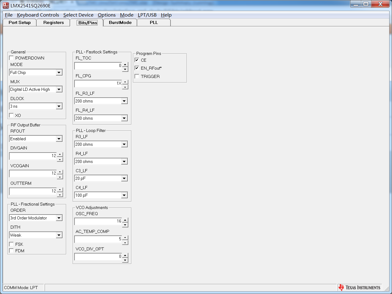
R7 0x00000017
R13 0x0000008D
R12 0x0000001C
R9 0x28001409
R8 0x0111CE58
R6 0x001F3326
R5 0xA0000005
R4 0x88019104
R3 0x00307F03
R2 0x04000642
R1 0x00000011
R0 0x001909C0

when i change the value of C3 and C4,the output frequency differ,but not my desired frequency. And the LD state is always unlocked(low). 

Is there anything wrong about the configuration above?

regard 

josh

  • Hi Josh,

    Thank you for your interest in our products. We received your question and will be answering it as soon as possible. We appreciate your patience.

    Regards,
    Julian
  • Josh,

    I see nothing wrong with your configuration.

    What I think could be happening is that the VCO is calibrating to the correct frequency band, which is getting you close in frequency.  However, the PLL is unable to lock to  this frequency.  I can't be sure why, but I could see this happening if, for instance, the loop filter output was not connected to the Vtune input.

    Regards,
    Dean

  •  thanks,Dean.

    you mean that the pin connection problem?

    This is the sch of the pll design.Is there anything wrong ?

  • while the pll can generate a output clock, is that the FPGA configure timing the cause of this problem? Because there are many constraint of the configuration timing.
  • Shiqi,

    I see nothing wrong with your schematic.   It would probably be helpful to narrow down what could be happening.

    Here are 3 possibilities:

    1.VCO Calibration Error

    The VCO could calibrate to a frequency that is close, but still a few MHz off.   One way that coudl happen is if you hold the LE pin high for too long on your programming interface, but there are other was to do this in software.   The device needs an input clock at the time of programming to ensure proper calibration.

    You can test this because if you measure the tuning voltage, it will be against the tuning rail.  Realize that the LMX2541 has an internal regulator, so the charge pump maximum voltage is likely around 2.5 V, not Vcc

    2.   Lock Detect Error

    If the tuning voltage seems well centered and the output frequency is correct, then perhaps it is an issue with lock detect.   When the phase detector frequency is higher or if in fractional mode, you need to be careful that this is not fooling the lock detect.  To diagnose, try reducing the modualtor order or phase detector frequency.  There is some discussion about this in the datasheet.

    Regards,
    Dean

  • hi,dean.
    I still cannot correct this problem . could any FPGA code provided? now i only need to output a single frequency.
    thank you.