This thread has been locked.

If you have a related question, please click the "Ask a related question" button in the top right corner. The newly created question will be automatically linked to this question.

LMX2485: Spurious Level Rejection

Genius 5355 points
Other Parts Discussed in Thread: LMX2485

Hi Support,

Please advise whether LMX2485 is a suitable device for the below spurious level rejection requirement as follow:

Component Limit      dBc
10 Hz to 100Hz        -28
100Hz to 3kHz         -40
3kHz to 10kHz         -50
10kHz to 100kHz     -60
>100kHz                    -60

Thanks.

  • Hi Ikon,
    I do not quite understand your question, here is my best guess.
    LMX2485 is a PLL, it requires an external VCO to complete a loop. The overall loop performance depends on your design as well as the configuration.
    If your configuration will create a spurs at, say 10kHz offset. maybe you need to design a loop filter with <10kHz bandwidth so that the spurs will be attenuated by the loop filter. Alternatively, maybe you can turn on Dither to randomize the spurs energy or maybe you can use a higher order delta sigma modulator to reduce the spurs.
    Summary, spurs frequencies and levels depend on the loop design as well as configuration. Our device is superior to others because we have special features to tackle spurs problem.
  • Hi Noel,

    Thanks.

    The eval board has this VCO part

    Crystem CVCO55BE-1800-2200
    www.crystek.com/.../CVCO55BE-1800-2200.pdf

    rather than
    www.crystek.com/.../CVCO55CL-0060-0110.pdf

    I wish to know if the supply voltage is 10V for this eval board.
    The VCO output is now -20dBm and not able to lock.

    Thanks.

  • Hi Ikon,

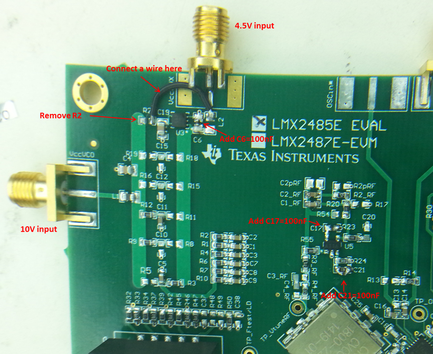
    You can do some modification to the EVM as below:

    To operate the board:

    Apply 10V to the SMA connector named VccVCO. This is the power supply to the VCO and the op-amp.

    Apply 4.5V to the SMA connector named VccAUX. This voltage will be regulated down to 3V for the rest of the circuitry. 

  • Hi Noel,

    I had applied the re-work detail mentioned below.
    On the code loader, I enabled the bits as given in the manual.

    10V input to the VccVCO, 4.5V to the VccAux, 50MHz clock 4dBm level was fed in to Oscin,  RFout connected to spectrum.

    I was trying to use PLLatinum sim to get the loop filter value. Attached is the file from SIM.
    C1_RF, C2_RF, C3_RF, C4_RF all DNA,
    R2_RF, R3_RF, R4_RF are mounted with some discrete value.
    I presume to change these parts following the value in PLLatinum SIM tool?

    Please advise.

    Thanks.

    4062.LMX2485.docx