This thread has been locked.

If you have a related question, please click the "Ask a related question" button in the top right corner. The newly created question will be automatically linked to this question.

RE: TRF372017: Carrier Leakage

Other Parts Discussed in Thread: TRF372017

Hi Yusuf,

       I have fed PRN sequence to IP and inverted PRN sequence(As we are interested in BPSK) to IQ.

QP and QN are left open.

I have tried varying DC offset to the PRN sequence, but no change in leakage.

Following is the RFOUT

Observed that carrier leakage is prominent.

How to suppress these carrier leakage?

Our PRN sequence was

and GUI settings

Set Up

Please suggest in detail as i'm new to this IQ modulation concepts.

Observation: If PWD_BB_VCM=0 then 1.7V observed at R2,R3 and R10,R11 (IC side)

If PWD_BB_VCM=1 then 1.2V observed at R2,R3 and R10,R11 (IC side)

Is it acceptable? (I hope R2,R3 and R10,R11 are capacitors).

Thanks,

Raghu

  • Hey Raghu,

    Have you tried adjusting I_offset under Reg7? Or I & Q off under reg 6? Also, try placing 50 ohm terminators on the QP & QN SMA inputs.

    Yusuf
  • Awaiting for your reply.

    Let me know if you need any further info.

  • I think you were not seeing the replies because the thread got too long so I split the thread. See Yusof's response above. The EVM is AC coupled and you have the internal Vcm engaged. The DC voltages should be around 1.7V on all I/Q pins as you report. Further DC offset optimization to improve carrier leakage can be done using the I/Q_OFF registers as Yusof mentions above.

    --RJH
  • Hi,

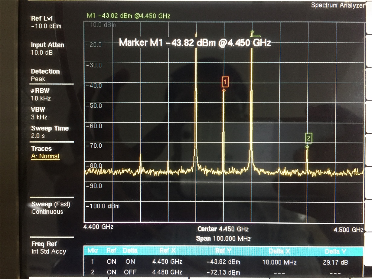
    Following is the RFOUT spectrum for Ip and In are 10MHz sine with phase offset(optimized). Qp=Qn=50ohm terminated.

    Inputs are AC coupled(EVM)

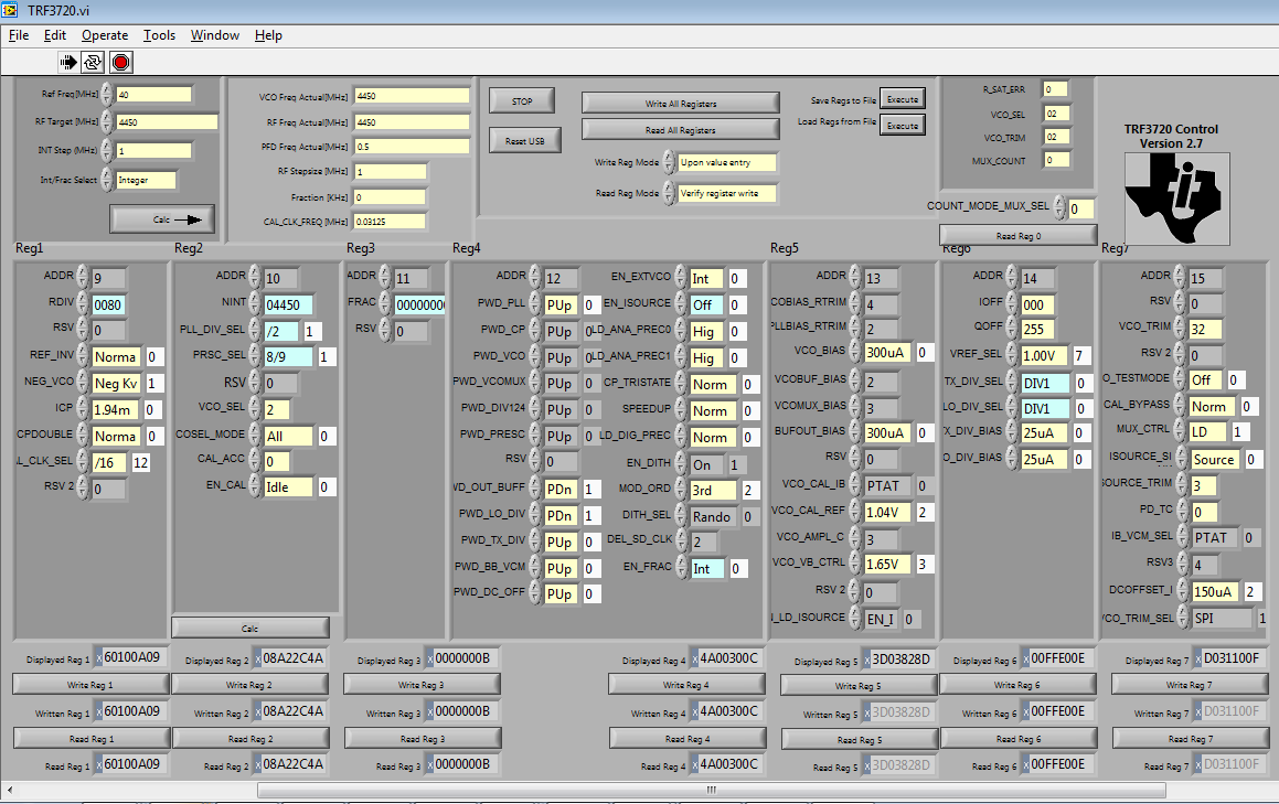
    GUI Settings

    I have optimized carrier leakage by adjusting the DCOFFSET_I, I_OFF, TX_DIV_BIAS, VCO_BIAS(Tried by varying all fields) .

    But i can only minimize up to -43 dBm.


    Regards,

    Raghu

  • In the screen shot it looks like you have railed IOFF to 0 and QOFF to 255. If this is giving you the best suppression then there is something not well balanced on the baseband paths.

    Reset the I/Q_OFF back to the default value (128). Performance should be around -35 to -40 dBm in this situation. Measure with a Volt-meter the DC levels at each of the baseband inputs. It should be around 1.7V and each input should be within a few mV of each other. If I/Q DC values in this scenario are way different (tenths of volts) then something is not right and the imbalance is beyond the tuning capability of the device.

    You may simply be overcompensating during your optimization. This is a common mistake. The adjustment for optimum performance takes a subtle touch because the optimized set-point is sensitive. Just a few steps away can make a big difference. I recommend to slowly adjust from default setting, first in steps of 10 and then in steps of 1 and alternating between I/Q registers.

    --RJH
  • Hi RJH/YUSUF,
    I have tried doing all your suggestions but unable to suppress the carrier below -30 dBm.
    Could you please share the settings and RF OUT screen shot if it is possible to suppress the carrier at least below -70 dBm in TRF372017 at 4.45 GHz.

    Regards,
    Raghu
  • Hi RJH/YUSUF,
    Thank you very much for your support. I can able to suppress the carrier leakage below -80 dBm.