This thread has been locked.

If you have a related question, please click the "Ask a related question" button in the top right corner. The newly created question will be automatically linked to this question.

TRF370417EVM: TRF370417EVM

Part Number: TRF370417EVM

Hello,

I'm trying to see the output of the TRF370417EVM evaluation module with only LO at the input as a first test. 

The module is biased with 5 V and I and Q ports are biased with 1.7 V and terminated with 50 Ohm. 

The LO frequency is 500 MHz..

What I see at the output is a lot of unwanted tones where tones at 2. 4 .6 GHz are dominating. 

Any idea what I'm doing wrong?

Kind regards,

Dragan

  • Dragon:

    You are likely seeing the harmonics generated by the modulator and your LO source generator. If all the BB input ports are biased to 1.7V and terminated then you should see your LO bleed-through at 500 MHz at about -40 dBm.  You will also see 2nd and 3rd and higher harmonics at similar levels...maybe a bit higher in some cases.  A high 13th harmonic at 6 GHz is unusual which leads me to think that the LO source is generating this.  Look at the harmonic content from your source to see if this is the case or filter the LO before injecting into the modulator.

    --RJH

  • Hello,

    You are right, most of these harmonics are very low (approximately -40 dBm). But there is always one ore more harmonics at about -10 dBm and the highest one is always at 4 times LO frequency. I tried to reduce the LO power and 4xLO harmonic does not respond much . I also tried to filter the LO but didn't get any improvement. I tested it at 500 MHz, 1 GHz and 1.5 GHz.

    Kind regards,
    Dragan
  • Dragan:

    You are seeing the normal operation from the device. The LO path, as part of the quadrature generation, uses limiters to fix the amplitude in each path which in turn generate harmonics. I did a quick test and see that indeed the 4th order harmonics are the worst (as are the 8th harmonics). In my testing, the LO bleed-through was around -40 dBm. 2nd and 3rd harmonics were 5-10 dB lower, and the 4th harmonic was at -25 dBm. At a 500 MHz input, the 8th harmonic was also at about -25 dBm. As the LO increases and the 4th harmonic (and higher) exceed the output BW capability of the device, those spurs diminish.

    In your application, I recommend to add a high frequency lower pass filter to eliminate the higher harmonic components that impact your system.
  • Hello,

    Thank you very much for the support and confirming the results. 

    Dragan 

  • Hi again,

    I have another question.

    The evaluation board is supplied with 5 V and the base band ports are supplied with 1.7 V using 1 uF capacitor as a DC block. Single tone signal is delivered to the I+ port and all the other ports are terminated with 50 Ohm. The LO is connected to the LOP port and LON is terminated with 50 Ohm.

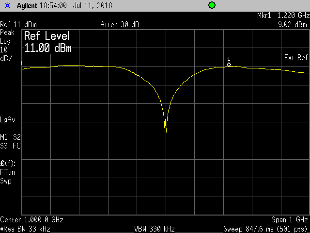
    The single tone signal is swept from 1 MHz to 500 MHz and the frequency response at the RF output is shown in the figure below. Amplitude of the base band signal is around 100 mV rms.

    Is the frequency response (the roll off at lower frequencies) for this scenario something I should expect? According to the datasheet it should work for kilohertz as well. 


  • Dragan:

    The baseband inputs need to supply the Vcm of 1.7V. There should not be a series DC block on the baseband inputs as that would block the common mode from getting to the device. Perhaps you are injecting the 1.7V via a wire to the BB port and using the cap to block it from the source.

    In any event, for testing, I typically use an Agilent ESG or equivalent that can generate differential I/Q signal and can set the common mode voltage. If you do not have access to this type of equipment, you can use a large pull-up resistor (i.e. 10kohm) connected to a variable power supply. The current draw will be low and the power supply can be tweaked to give the desired Vcm.

    If you have a series capacitor then you are seeing the impact of a RC (or would you say CR) high pass filter with a series C (DC blocking cap) and the internal (shunt) resistance of the device. If you eliminate the cap, this issue will be resolved.

    --RJH
  • Hello,

    So basically this part can only be used as AC coupled?

    We want to use this part with AC coupled DAC module. Is there a way of doing that?

    Best regards,

    Dragan


  • The part is designed to be DC coupled where the DAC provides the proper common mode voltage or a voltage translation circuit is used to transform the DAC voltage to the proper Vcm voltage. There is probably a way to DC interface whichever DAC that you are interested in using.

    If you must be AC coupled then make the AC cap big (i.e. 1 uF) to keep the high pass corner as low as possible. Then you will need to add in the DC common mode voltage post AC cap through a voltage divider or the like.

    --RJH