This thread has been locked.

If you have a related question, please click the "Ask a related question" button in the top right corner. The newly created question will be automatically linked to this question.

ADS58J89EVM: Connecting this device to FPGA

Part Number: ADS58J89EVM

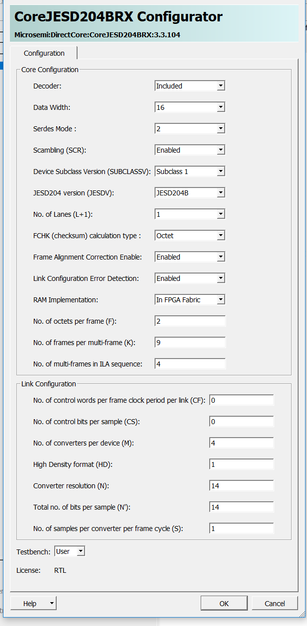
I'm trying to interface a ADS58J89EVM to a Microsemi Smartfusion 2 FPGA. I've been reading through the docs, and there has been a lot of conflicting information that would be awesome to clear up.  My main issue is that I'm having trouble pulling and reading data off this device. I read in one document that it uses JESD204B to transfer data, but there seems to be a lack of pins to support this function. In another document, it seems that it uses a SPI interface to transfer data, but I can't find the pins to support this either. What I have found is that there is 8 output pins that might carry data, but I'm not sure the protocol they use. Is there some document/s that could best streamline my grasping of this concept, or can I get a clarification about how this can be accomplished?

As a sidenote, I am also looking for other ways to accomplish a 'ADC-to-filter-to-DAC' problem in real-time. I was kind of just handed these components (TI ADC, Microsemi FPGA, TI DAC) and I'm unsure whether or not they're suited to get the job done.

  • Hi,

    Refer to page 4, pin out description, Data Output Interface pins for JESD204B data transfer pins.

    Refer to page 4, pin out description, Control or Serial for SPI access.

    I am not sure how to answer "ADC to filter to DAC" problems.... This is a very generic problem. Please be a bit more specific. Thank you.

  • Thanks for the response. 

    The pinout, on that area of the document, is insufficient information for me to get to the answer I'm looking for.

    My first question is: Do I have a choice of using SPI or JESD204B to interface with the this device? Or do I use one to gain access to the other?

    Second, I'm trying to connect this component (ADS58J89) to an IP core (CoreJesd204BRX) that Microsemi provides. There are LMFS settings that are provided on this document, but, there are a litany of other settings that I'm having trouble filling out for the core. I'll attach a picture of this. Could I get a more clear explanation of how am to choose these settings?

    a

    Another issue I'm having is actually sourcing the pins, on the fmc adapter of the ADS, to the pins that are listed on the document you are referring to.  This document:

    shows the some of the pins that are needed for JESD204BRX, but they seem to be inputs. There is also pins SPI_D0-D8 which seem to be outputs. This is the conflicting information I was talking about. Some clarification about how to read this document (or a better document) would be great.

    Thanks!

  • Hi,

    The SPI is mainly used to configured the ADC device, while the JESD204 bus is used for high speed data transfer from ADC to FPGA

    It is best for you to start learning about JESD204 from our TI learning center to get an idea on the JESD204 protocol

    we cannot offer support on the Microsemi IP configurator. You will need to contact your local Microsemi support for help.

    I recommend you also seek support from your internal team for additional guidance on your project. The understanding of SPI and JESD204 are critical on a system level planning. Someone on your team should give you some guidance on how the overall system design from FPGA, ADC, to front end design and the goal of the system. You will need a good overall picture to have a good design.

    The number of lanes, the lane speed, and also the lane configuration on the LMFS will need to come from your team as they are applications specific. TI cannot provide guidance on how your system should operate. Sorry about this. 

    -Kang