This thread has been locked.

If you have a related question, please click the "Ask a related question" button in the top right corner. The newly created question will be automatically linked to this question.

IWR6843ISK: How to Config for Range up to 14 meter on People Counting Lab

Part Number: IWR6843ISK
Other Parts Discussed in Thread: IWR6843

Hi Teams,

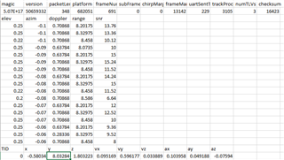
I found that the IWR6843 ISK report on Y value always LESS than 7 meter even be configed by the configuration file for 14 meter 

The working lab is based on the Tool Version as followings,

- CCS 8.3.1

- SDK 3.5.0.4

- Industrial Tool 4.7.0

- Lab: People Counting

- Config: IWR6843 ISK 14 m (based on TI configuration file)


Regards,

Kevin

  • Hello Kevin,

    Can you please give more information what you are looking at to say the Y value is always less than 7? I just verified that the recorded value is >7 when I walked to about 8m from the sensor using the 14m default cfg.

    How are you running the sensor and verifying the output?

    Regards,

    Jackson

  • Hi Jackson,

    (1) Please checking the following picture,

         for example: at the row 3 on the POS=(x, y, z) shown y value '+06.485'

    (2) More information what cfg file be used,

         - File Location: C:\ti\mmwave_industrial_toolbox_4_7_0\labs\people_counting\68xx_3D_people_counting \chirp_configs\ISK_14m_extended.cfg

         - File Content:

    sensorStop
    flushCfg
    dfeDataOutputMode 1
    channelCfg 15 7 0
    adcCfg 2 1
    adcbufCfg -1 0 1 1 1
    lowPower 0 0
    profileCfg 0 60.75 30.00 25.00 59.10 657930 0 27 1   96 2950.00 2 1 36
    chirpCfg 0 0 0 0 0 0 0 1
    chirpCfg 1 1 0 0 0 0 0 2
    chirpCfg 2 2 0 0 0 0 0 4
    frameCfg 0 2  96  0 100.00 1 0    // ALERT: changed as 100.00 from 55.00
    dynamicRACfarCfg -1 4 4 2 2 8 12 4 8 5.00 8.00 0.40 1 1
    staticRACfarCfg -1 6 2 2 2 8 8 6 4 8.00 15.00 0.30 0 0
    dynamicRangeAngleCfg -1 0.75 0.0010 1 0
    dynamic2DAngleCfg -1 1.5 0.0300 1 0 1 0.30 0.85 8.00
    staticRangeAngleCfg -1 0 8 8
    antGeometry0 0 -1 -2 -3 -2 -3 -4 -5 -4 -5 -6 -7
    antGeometry1 -1 -1 -1 -1 0 0 0 0 -1 -1 -1 -1
    antPhaseRot 1 1 1 1 1 1 1 1 1 1 1 1
    fovCfg -1 70.0 20.0
    compRangeBiasAndRxChanPhase 0 1 0 1 0 1 0 1 0 1 0 1 0 1 0 1 0 1 0 1 0 1 0 1 0
    staticBoundaryBox -3 3 2 10 0 3
    boundaryBox -4 4 0.5 12 0 3
    sensorPosition 2 0 15
    gatingParam 3 2 2 2 4
    stateParam 3 3 6 500 5 6000
    allocationParam 40 100 0.1 10 0.5 20
    maxAcceleration 0.1 0.1 0.1
    trackingCfg 1 2 800 30 46 96 55
    presenceBoundaryBox -4 4 0.5 12 0 3
    sensorStart

    (3) I had done some tests that the Y value can be found up to 7 m but LESS then 8 m when I walked to 14 m

    Regards,

    Kevin

  • Hi Jackson,

    I had done some tests that the Y value can be found up to 7 m but LESS then 8 m when I walked to 14 m

    Please check at row 7 show y value '+07.715'

    Regards,

    Kevin

  • Hello Kevin,

    How are you parsing the TLVs, it looks like you are running this inside Teraterm?

    A few notes. Please make sure you are mounting the sensor according to the sensorPosition parameters (the default is 2m high and 15 degree tilt). Make sure you adjust the boundary box, even though the default profile is set for 14m detection, the boundary box limits tracking to 12m.

    It seems you modified the frame rate from 55ms to 100ms in the frameCfg parameter. This will also need to be modified in the trackingcfg parameter as well to match. Please see the following documentation for information about tuning the tracker.

    3D_people_counting_tracker_layer_tuning_guide.pdf

    Regards,

    Jackson

  • Hi Jackson,

    (1) I comment out the original MagicWordHeader, TargetList and TargetIndex etc codes

        and write a short codes instead on MmwDemo_uartTxTask() in mss_main.c

        as followings,

    //*************************************************************************************************************

    //* show TID, POS, VEL, ACC results in READABLE format

    //* via UART DATA port with baud rate 921600 by Tera Term

                static uint32_t JBL_U32 = 0L;
                static uint32_t JBL_targetNumberU32 = 0L;
                static uint32_t JBL_U8 = 0;

                //* FLOW
                JBL_U8 = (JBL_U32++ % 10) + '0'; // show '0'..'9'

                UART_write(uartHandle, "JB> flow=", sizeof("JB> flow="));
                UART_write(uartHandle, &JBL_U8, 1);

                #if(1) // show TID, POS, VEL, ACC; ALERT: just show only ONE target here
                //* TARGET NUMBER, 112 := length of structure TARGET LIST
                JBL_targetNumberU32 = (targetListLength - sizeof(Pcount3DDemo_output_message_tl)) / 112;
                UART_write(uartHandle, ", TAR=(", sizeof(", TAR=("));
                jb_UART_writeU32(uartHandle, JBL_targetNumberU32);
                //* TID
                UART_write(uartHandle, "), TID=(", sizeof("), TID=("));
                jb_UART_writeU32(uartHandle, (gMmwMssMCB.trackerOutput.tList[gMmwMssMCB.trackerOutput.currentDescr]->tid));
                //* POS
                UART_write(uartHandle, "), POS=(", sizeof("), POS=("));
                jb_UART_write(uartHandle, gMmwMssMCB.trackerOutput.tList[gMmwMssMCB.trackerOutput.currentDescr]->posX);
                UART_write(uartHandle, ",", 1);
                jb_UART_write(uartHandle, gMmwMssMCB.trackerOutput.tList[gMmwMssMCB.trackerOutput.currentDescr]->posY);
                UART_write(uartHandle, ",", 1);
                jb_UART_write(uartHandle, gMmwMssMCB.trackerOutput.tList[gMmwMssMCB.trackerOutput.currentDescr]->posZ);
                //* VEL
                UART_write(uartHandle, "), VEL=(", sizeof("), VEL=("));
                jb_UART_write(uartHandle, gMmwMssMCB.trackerOutput.tList[gMmwMssMCB.trackerOutput.currentDescr]->velX);
                UART_write(uartHandle, ",", 1);
                jb_UART_write(uartHandle, gMmwMssMCB.trackerOutput.tList[gMmwMssMCB.trackerOutput.currentDescr]->velY);
                UART_write(uartHandle, ",", 1);
                jb_UART_write(uartHandle, gMmwMssMCB.trackerOutput.tList[gMmwMssMCB.trackerOutput.currentDescr]->velZ);
                //* ACC
                UART_write(uartHandle, "), ACC=(", sizeof("), ACC=("));
                jb_UART_write(uartHandle, gMmwMssMCB.trackerOutput.tList[gMmwMssMCB.trackerOutput.currentDescr]->accX);
                UART_write(uartHandle, ",", 1);
                jb_UART_write(uartHandle, gMmwMssMCB.trackerOutput.tList[gMmwMssMCB.trackerOutput.currentDescr]->accY);
                UART_write(uartHandle, ",", 1);
                jb_UART_write(uartHandle, gMmwMssMCB.trackerOutput.tList[gMmwMssMCB.trackerOutput.currentDescr]->accZ);
                UART_write(uartHandle, ")\n", sizeof(")\n"));
                #endif

    //*************************************************************************************************************

    (2) The sensor is mounted 2m high and 15 degree tilt

    (3) The parameters of configuartion on boundary,

    staticBoundaryBox -3 3 2 10 0 3
    boundaryBox -4 4 0.5 12 0 3
    sensorPosition 2 0 15
    gatingParam 3 2 2 2 4
    stateParam 3 3 6 500 5 6000
    allocationParam 40 100 0.1 10 0.5 20
    maxAcceleration 0.1 0.1 0.1
    trackingCfg 1 2 800 30 46 96 55
    presenceBoundaryBox -4 4 0.5 12 0 3

    (4) I will try again on change back the original frame rate setting as 55 ms

        Any suggest?

    Regards,

    Kevin

  • Hi Kevin,

    Any frame rate between 55ms and 250ms should work ok. If you increase the frame rate too much, there isn't enough time to send out all the UART data. If you decrease the framerate too much, the tracking performance could degrade. Just make sure to change both frame rates to be the same.

    Regards,

    Jackson

  • Hi Jackson,

    The largest distance measured up to 11.063 meter when the frame rate changed back as 55 ms

    Regards,

    Kevin