This thread has been locked.

If you have a related question, please click the "Ask a related question" button in the top right corner. The newly created question will be automatically linked to this question.

AWR1843BOOST: Virtual array antenna in the MRR lab

Part Number: AWR1843BOOST
Other Parts Discussed in Thread: AWR1843AOP

Hi,

I'm working with the AWR1843BOOST with a custom antenna array and I'm trying to use this array in the MRR lab. I read in other posts that it is necessary modify the azieleprocessing() function.

I already modified it but I'm not sure that it is all. It is need any modification more to use my custom array antenna?


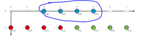
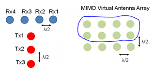
My array is very similar to AWR1843AOP. I have 4 antennas in azimuth and 3 in elevation. My changes are:

if(obj->numTxAntennas == 3)
		{
            /* Populate the third four. Antenna Tx1 [8,9,10,11] */
            for (rxAntIdx = 0; rxAntIdx < (obj->numRxAntennas); rxAntIdx++)
            {
                obj->azimuthIn[rxAntIdx].real = obj->antInp[rxAntIdx+(2*(obj->numRxAntennas))].real/4;
                obj->azimuthIn[rxAntIdx].imag = obj->antInp[rxAntIdx+(2*(obj->numRxAntennas))].imag/4;
            }

            /* Populate the second four. Antenna Tx2 [4,5,6,7] */
            for (rxAntIdx = 0; rxAntIdx < (obj->numRxAntennas); rxAntIdx++)
            {
                /* The 'virtual antenna' corresponding to the tx is offset in elevation. */
                obj->elevationIn[rxAntIdx].real = obj->antInp[rxAntIdx + obj->numRxAntennas].real/4;
                obj->elevationIn[rxAntIdx].imag = obj->antInp[rxAntIdx + obj->numRxAntennas].imag/4;
            }


            /* Populate the first four. Antenna Tx3 [0,1,2,3] */
            for (rxAntIdx = 0; rxAntIdx < (obj->numRxAntennas); rxAntIdx++)
            {
                /* The 'virtual antenna' corresponding to the tx is offset in elevation. */
                obj->elevationIn2[rxAntIdx].real = obj->antInp[rxAntIdx].real/4;
                obj->elevationIn2[rxAntIdx].imag = obj->antInp[rxAntIdx].imag/4;
            }

		}

On the other hand, I would like to use the SRR lab with my custom virtual array antenna, how I change the virtual array in the SRR lab or what changes are necessary?

Thanks

  • Hi,

    The MRR demo has two modes USRR and SRR

    Running the MRR mode on your customer board would be easy since there are no significant changes needed for angle estimation.

    Did you try to run it already?

    Running the USRR mode on your customer board will require significant changes because it will change the angle detection significantly.

    Based on your code changes I can see that you want to run the USRR mode that includes elevation as well.

    Unfortunately we have not ported yet the MRR/USRR demo to AOP. So we don't have a validated implementation.

    I will review your code in more details and see if I can make any suggestions

    Thank you

    Cesar

  • No, I didn't try yet but I will make the test. I'm very interested in the USRR mode because I would like to detect in static or movement nearby objects. What changes are necessary to implement the USRR mode in my custom board or how can I do these changes?

    I also made changes at dss_main.c:

        obj->processingPath = POINT_CLOUD_PROCESSING;
        obj->subframeIndx = subframeIndx;
        obj->numRxAntennas = NUM_RX_CHANNELS;
        obj->chirpThreshold = ADCBUFF_CHIRP_THRESHOLD;
        obj->numTxAntennas = SUBFRAME_USRR_NUM_TX;
        obj->numVirtualAntennas = SUBFRAME_USRR_NUM_VIRT_ANT;
        obj->numVirtualAntAzim = 4;
        obj->numVirtualAntElev = 8;
        obj->numAdcSamples = SUBFRAME_USRR_NUM_CMPLX_ADC_SAMPLES;
        obj->numRangeBins = SUBFRAME_USRR_NUM_CMPLX_ADC_SAMPLES;
        obj->numChirpsPerChirpType = SUBFRAME_USRR_CHIRPTYPE_0_NUM_CHIRPS;
        obj->numAngleBins = SUBFRAME_USRR_NUM_ANGLE_BINS;
        obj->invNumAngleBins = 1.0f/((float)SUBFRAME_USRR_NUM_ANGLE_BINS);
        obj->numDopplerBins = SUBFRAME_USRR_CHIRPTYPE_0_NUM_CHIRPS;
        obj->maxNumObj2DRaw = MAX_DET_OBJECTS_RAW_POINT_CLOUD_PROCESSING;

    Anyway, I will wait your suggestions.

    Thanks

  • Hi,

    I need to discuss with demo developer potential changes.

    Why did you set " obj->numVirtualAntElev = 8;"? With the custom antenna there are 3 antennae in elevation.

    The antenna virtual array should be similar to the AOP

    https://www.ti.com/lit/ug/tiduez2/tiduez2.pdf?ts=1621023812288&ref_url=https%253A%252F%252Fwww.ti.com%252Ftool%252FTIDEP-01024

    See "2.3.1.2 Antenna Configuration"

    Thank you

    cesar

  • Hi,

    Based on the original code of the MRR I thought that obj-> numVirtualAntElev = 4 refers to the virtual array of the AWR1843BOOST has in total four antennas in elevation, not for level, so I thought it was the correct nomenclature

    Then, I understand that there is other nomenclature and numVirtualAntElev refers to the number of antennas for each level and so, the correct code nomenclature on the AWR1843AOP is:

    I think I was wrong so, the correct code nomenclature in the AWR1843AOP is:

    obj->numVirtualAntAzim = 4;
    obj->numVirtualAntElev = 4;

    Can you tell me if it is correct?


    Thanks for the aclaration.

  • Hi,

    Your understanding of which virtual antennae are used for elevation is not correct.

    Fig 2.5 and Fig 2.6 are the virtual antennae used for elevation and aziumth for AOP.

    Thank you

    Cesar