This thread has been locked.

If you have a related question, please click the "Ask a related question" button in the top right corner. The newly created question will be automatically linked to this question.

TDC7201-ZAX-EVM: TDC7201-ZAX-EVM

Part Number: TDC7201-ZAX-EVM
Other Parts Discussed in Thread: TDC7201

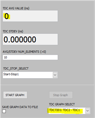
Hello TI Team, for a project work I would like to calculate  and show the distance by using the TDC AVG value. My opinion is to integrate this into the Gui for the TDC7201EVM. May I now does this function already exists or can you please share the source code with me?

If not will the TDC avg value calclated by the microcontroller? If yes how can I read out this value by UART with Matlab? Or will this value been calculated by the GUI?

Thank you very much for your feedback.

Best regards,

Lars

  • Hello Lars,

    Thanks for the question. The GUI currently does not have the functionality to turn the Time of Flight into a distance measurement.

    I have not checked the source code so I cannot confirm this 100% but I believe the TDC avg value is calculated by the microcontroller using the formulas value found in section 7.4.2 of the data sheet, they are indicated as TOFn. The formula used is dependent on the measurement mode the device is in. Unfortunately I do not believe the TDC Avg Value is transmitted via UART at any point on the EVM since it transmits that data through USB.

    What you should be able to do is obtain the values of the other registers used to calculate for the TOF, all the data you need should be transmitted via UART between the microcontroller and the device. You can simply read that data being transmitted and perform the calculation in Matlab. Hopefully this answers your question.

    Best,

    Isaac

  • Hello Isaac,

    Thank you very much for your feedback. Ok understand, may I then it's possible to share the source code with me from the GUI?

    We are doing an short time measurement with the GUI and our TOF is stop TDC2 - Stop TDC1 as shown in the picture:

    From your explanation it should be possible to read out the TDC2 stop time and TDC1 stop time and then do the calculation in Matlab correct? Can I read out this Data by the Uart debug interface from the MSP, since I need the other Interface to communicate between the MSP and the GUI? Do you now the registers were this two informations are transmitted by Uart. I'm new in reading out data by Uart, so I'm open for every help.

    Thank you.

    Best regards,

    Lars

  • Hello Lars,

    Unfortunately I am not able to provide the GUI source code. 

    But like I mentioned it is definitely possible to read the necessary registers in order to make the calculation via Matlab or another external microcontroller. I did accidentally misstate the type of communication that is occurring on the TDC7201, it is actually SPI instead of UART.

    The data that needs to be read from the device are the ones necessary in order to calculate the ToF since TDC2 avg and TDC1 avg are calculated in the MCU. So the device transmits the registers needed to calculate this data.

    For example register needed for mode 1 are dependent on this formula assuming single stop:

    Registers needed are:

    TIME1: register address 0x10

    CALIBRATION1: register address 0x1B

    CALIBRATION2: register address 0x1C

    Known values:

    Clock Period

    Calibration2_Periods

    This is an example of the SPI communication when reading a register TDCx_CONFIG1 register 0, with the device in mode two:

    This is an example of the SPI communication when reading a register TDCx_CONFIG2 register 1, with the device in two stops and 10 calibration clock periods:

    You can decipher what the registers are telling you by looking at the register maps. Keep in mind some registers on the device are 8 bit registers like the ones I showed here and there are some others that are 24 bits long. The register map can be found in section 7.6 of the datasheet.

    Best,

    Isaac

  • Hello Isaac,

    Thank you again for the further explanation. Now I understand the situation much better, but I have to explain it more in detail, that we are talking about the same situation. We are using the TDC7201EVM in combination with the MSP430F5529LP. So from my understanding, when we are doing the following measurement:

    The TDC1 will measure T1 and TDC2 will measure T2. Both informations will be sent to MSP430 and the MSP 430 will then calculate the TDC avg time  with the calculated T3 times as marked in my text befor. This time will then be transmitted from the MSP430 to the GUI. As I understand the situation. I would like to read out this value from the MSP430 by the interface UART to calculate in Matlab the distance. Uart stream can be activated in the GUI.

    Since I need Com5 to Run the GUI with the MSP

    I think this should be not very complex but I haven't found any informations in which register map this information will be transmitted from the MSP to the GUI and how I can read out this information by UART.

    Would be very good if you can support me with this information. Thank you.

    Best regards,

    Lars

  • Hello Lars,

    Thank you for the clarification to your question. I am unfamiliar with how the data is transmitted via USB and whether or not the information is transmitted via UART.

    The reason I say this is because if you try to connect the GUI to COM3 (MSP Application UART1 on your system) it will yield an error. So to me it seems the case that the information is probably not flowing through the UART comport noted. As mentioned, COM5 (on your system) seems to be the one used to bridge the communication between the GUI and the MSP430. My suggestions would be the following:

    If you are able to use a USB sniffer or USB analyzer in order to check the incoming data packets on COM5, this will give you an idea of how the data is being transmitted to the GUI and perhaps give you a clue on to how it can be extracted to use for calculations in Matlab.

    The second suggestion would be to go to the TI Resource Explorer. Where you can find code examples for the MSP430F5529LP in specific on how USB communications are programmed furthermore helping you identify how the data is actually being transmitted to the GUI.

    I wish I could be of more service here but I believe that if the EVM is going to be used then the simplest way to be obtain the information into Matlab would be to use SPI communication which Matlab is capable of doing. I hope this helps!

    Best,

    Isaac

  • Hello Issac,

    Thank you again for your feedback.

    I tried it with the USB-Sniffer for COM5. I can receive some date but they are really unsorted and no definition, which would give me an clue which data I should read out by matlab.

    So please share the source code with me, I saw some case in the Forum were the source code was shared by private messages. Or then make a meesage to the resposible devolper that they can add this function to the GUI. I think this would be very helpful for a lot of people whow do the first Lidar projects with the TCD720XEVM and the GUI. I think it's not so a big effort to add this function into the Gui.

    Best regards and have a good weekend,

    Lars

  • Hello Lars,

    Sorry to hear that the sniffer was not very helpful, it could be that the sniffer doesnt sort through the packets the same way the GUI would. Unfortunately I am still not able to provide the source code for the firmware, sometimes you may see exchanges like that occur in the forum but these post may come from other internal TI employees to whom we can share the source code with.

    Currently there are no plans to add additional functionality to the TDC720XEVM GUI, but I did find something you can reference that you might find helpful. You can find the firmware code for the MSP430 that transmits the information via USB. If you chose the standard setup it can be found in the following path: C:\Program Files (x86)\Texas Instruments\TDC720xEVM\Firmware\TDC720xEVM_Firmware_Source-v2.07.zip. It might not be the most ideal method but you can follow the dataflow in the code to see how the data is being transmitted via USB.

    I still believe that SPI communication through Matlab would be a viable solution. I found this video on the Matlab website where they use a Raspberry Pi to handle communicate between Matlab and other various sensors: https://www.mathworks.com/videos/collect-and-analyze-data-using-matlab-and-raspberry-pi-92959.html

    I hope this helps, and have a good weekend as well.

    Best,

    Isaac