This thread has been locked.

If you have a related question, please click the "Ask a related question" button in the top right corner. The newly created question will be automatically linked to this question.

DRV5056-Q1: Why does it need a resistor between VCC and OUT?

Part Number: DRV5056-Q1


Hi team, 

Why does DRV5056-Q1 need a resistor between VCC and OUT shown in figure 14?

Could you confirm my understanding written in lower list correct?

1) This device operates correctly or shows linear output following along its magnetic field even if there is no resistor between VCC and VOUT.

2) You recommend using this resistor for short or open event detection shown in table 1.

If there are misunderstandings, please let me know your comment.

Regards,
Ochi

  • Hi Ochi-san,

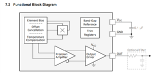
    When you are referring to Figure 14, are you referring to the functional block diagram picture below?

    If so, the resistor is not between VCC and OUT for this particular figure.  The resistor that is shown in the figure above is an optional filter to reduce the noise if you don’t need to use the full 20 kHz bandwidth of the device, as is described in section 8.1.3 of the datasheet. 

    As you mentioned, the device does not need a resistor to produce the linear magnetic response output seen in Figure 16.  The resistor in table 1 is just needed if your application needs to also detect if interconnect wires become open or shorted.

    Regards,

    Mekre