This thread has been locked.

If you have a related question, please click the "Ask a related question" button in the top right corner. The newly created question will be automatically linked to this question.

TUSS4440: Propogation Delay

Part Number: TUSS4440

Hello,

I am using the TUSS4440 with Prowave 400EP18-NBPN transducer for ultrasonic distance sensing and am noticing my results from the comparator (OUT4) are showing about 500us greater than what I expect for a given distance at my testing temperature.  I don't see any mention of propagation delays through the AFE and wanted to ask what might account for this 500us.  I would think the amplifiers would be on the order of nanoseconds, but wanted to ask.  Another item I'm not sure about is how I should consider multiple pulses; I am using 16 pulses at 40kHz which accounts for 400us.  Should I be using timing from the start of pulses or from the end?

I appreciate your insight on what might be causing the error we are seeing.

Kind Regards,
-Jon

  • Hello Jon,

    Thank you for your question. I have not seen anything come in regarding a propagation delay on OUT4, and I wont be able to look into this until tomorrow. For now, would you mind sending me your device settings as well as the voltage in which your driving the transducer at?

    Best,

    Isaac

  • Thanks for such quick response Isaac, I'm very glad to hear you'll be able to look at this tomorrow.  As noted, I would be surprised if it's propogation through the amplifiers but wanted to ask as I couldn't find the spec in the datasheet.  I'm leaning towards more not understanding whether timing should be from the start or end of multiple pulses.  Perhaps there is other propogation to consider (e.g. cabling?)

    We are using a 1:8.4 transformer from 5V and are seeing about 80Vp-p on the first pulse which decays to about 64V by the 16th pulse, followed by some ringing.  Here is a capture of this response.

    Regarding settings, I'm not sure which ones you want.  We have current set to 250mA, pulses set to 16, IO_MODE 1 (CTRL_3= 0x01), CTRL_2 = (CTRL2_LNA_G10 | CTRL2_LNA_3V | RNG1_LOGAMP_GAIN).  If there are additional information you need please let me know.

    Thank you,
    -Jon

  • Hello Jon,

    I had to make sure how it would be done on this device since we do have another that is a bit different but it seems like the measurement is taken at the beginning of the pulse train. Was the 500us propagation delay you were observing taking the measurement from the beginning of the pulse train or towards the end?

    Best,

    Isaac

  • Yes, we are starting the timing at the beginning of the pulse train.

  • Hey Jon,

    Okay just to clarify with the pulse train starting at the beginning are you seeing a 500us delay or the 100us that are not accounted for?

    Is there any way you can obtain a scope shot of the VOUT data and the comparator output OUT4? I want to see if the delay may be coming from the comparator itself or in one of the earlier stages. I did not see a delay on my end but perhaps it could be since I did not test with your exact settings or you could have a damaged device.

    The other check we can do is to probe both the OUTA and OUTB output pins as well as the VOUT data and this should give us a better indication as to what the propagation delay could be as it goes through the different stages (LNA->BPF->Log Amp->LPF). Ideally we should see very little shift in the data.

    Best,

    Isaac

  • Hey Isaac,

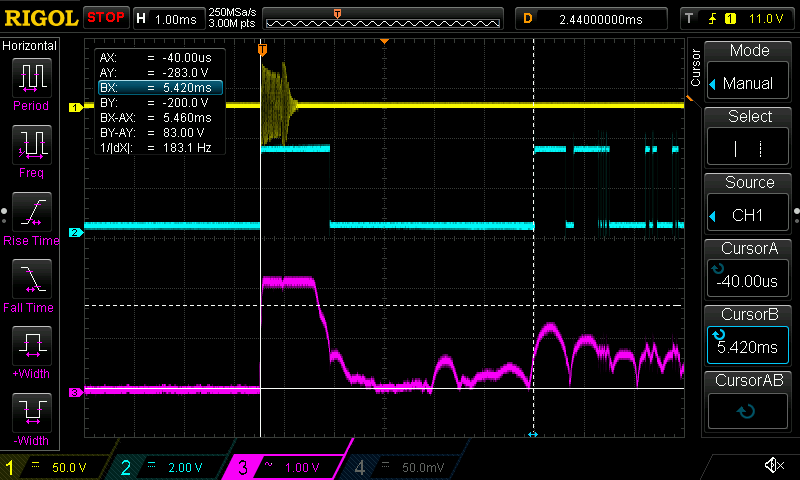
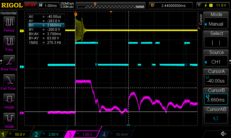
    The time we are seeing is longer than expected.  From previous testing, we were seeing around 500us.  I did a test today to give you screen captures and am finding only 110-140us; I'm not quite sure why I don't see as much issue as before but still would appreciate your insight on what might be causing this.  Note that I did use a high accuracy thermometer to measure 70F in my test today, correlating with 13536 in/s.  For 24" this should be 3.55ms while we see 3.66 (110us, or 0.77" error) and for 36" this should be 5.32ms while we're seeing 5.46ms (140us, or 0.95" error).

    Here are the two captures.  Ch1 is the transducer, Ch2 is OUT4, and Ch3 is AOUT.  When zooming in I can confirm that there is minimal difference between when AOUT rises above 1V and when OUT4 rises.

    36"

    24"

    I appreciate any thoughts you have.
    Thank you,
    -Jon

  • Hello Jon,

    Thank you for the screen captures. I am glad to hear that the measurements are not that far off from where they should be. Have you attempted to change the value of the comparator threshold to see if that can trigger OUT4 at a more ideal time? It may be a little bit difficult if there is too much noise on the receiver.

    I did find something interesting on the data sheet regarding C_FLT, it seems like this capacitor can slow down the response time of the log amp. Perhaps adjusting this value could get you closer to the real ToF value you should be seeing on the comparator. I have attached the excerpt below, you can find it in section 7.3.4 of the datasheet linked here.

    Cinp and Rinp could possible also be contributing to the small delay as well. I know the 3k resistor is not needed and it only recommended for EMI noise immunity, not sure if you have the ability to replace this resistor on the board in order to test if the resistor is doing much in terms of delay but I suspect the capacitor might be the one doing most of the work on that end. Unfortunately I believe that capacitor is recommended to protect the input.

    Upon making some more exact measurements I am also observed a similar delay in my measurements but was slightly corrected when I fine tuned the setup. The issue with ultrasonic sensing is that there are a lot of mechanical variances that could be causing issues, in my scenario the surface which I was targeting was a little bit slanted and I assume there was some delay from when the sound waves were reflecting and reaching the transducer adding to my delay.

    But I believe if you can define the delay that you are seeing on your end you should be able to factor some of it into your final measurement in order to obtain a closer value.

    Best,

    Isaac

  • Hey Issac.

    We have experimented with different thresholds, however as you noted striking a balance between noise and maximum distance is what lead us to 1V setting.  I agree that it seems there is some delay there for Aout to reach the threshold and this is likely part of the issue.  Sounds like your comment on section 7.3.4 relates to this rise time.  We are using a value of 2.2nF here, while the equation 3 comes out to 16nF at our 40kHz.  There isn't mention of how to calculate what the delay would be based on value of Cfilt though, do you have any thoughts on this or is using a scope to measure a reasonable solution?

    As Cinp and Rinp have quite a small time constant (330pF * 3kohm = 0.99us), that doesn't seem to be a significant portion of the error we're seeing.

    Do you have any recommendation on how to 'define the delay' we're seeing?  Is it as simple as making an accurate measurement of distance for a test, collecting the time recorded, and comparing it to what is expected based on speed of sound considering humidity and temperature of the test environment?  Should we measure across multiple PCBA's, transducers, and distances?  I appreciate any insight you have so we get an accurate compensation in here.

    Thank you,
    -Jon

  • Hello Jon,

    I agree that the time constant from Cinp and Rinp is likely not the issue due to the small capacitance. Unfortunately I have not done much testing in the past on changing the CFLT capacitor, I am currently using a 3.3nF & 40kHz transducer as well. I changed it to a 15nF for a quick test and it did seem to increase my ToF measurement slightly maybe like ~40-50us, but once I tried to populate something very small 800pF I was not able to get a good reading.

    I believe that using the scope as you suggested might be the best approach at the moment. Testing various PCBA's, transducers, and distances would probably yield the best results because you could identify if the delay is similar across different setups and compensate for this appropriately in your post processing of the data. As far as temperature and humidity go then I would only take those into consideration if your system is taking those into consideration as well. This should help you obtain better results.

    Another thing to note is that for higher accuracy systems a higher frequency transducer is typically used. The 40kHz transducers are seen in longer range applications. Using a higher frequency transducer gives you better system resolution, not sure if that's also a factor into the measurements you are taking here but thought I would give you a heads up. I have not attempted these more precise measurements with this setup on my end.

    Best,

    Isaac

  • Thank you Issac.  We are looking to go up to 144" so I think the 40kHz is a reasonable choice, but appreciate your suggestion none-the-less.

    We'll plan to perform testing to figure out what compensation value to use, noting that the key factors seem to be Cfilt value, comparator threshold level, and propagation through various stages.

    I appreciate your support.

  • Any day Jon, always glad to help out. Enjoy your upcoming holiday.

    Best,

    Isaac