


Other Parts Discussed in Thread: AWR1843
Hello,
In Beamsteering for Corner Radar Reference Design
I am confused about the step size which is 30 degree in figure 1 and step size which is 20 degree in figure 2.
Q1. What's the difference between these step sizes?
Q2. How to set the step size and the steering angle between -+60 to -+80 just as an example in the firmware?
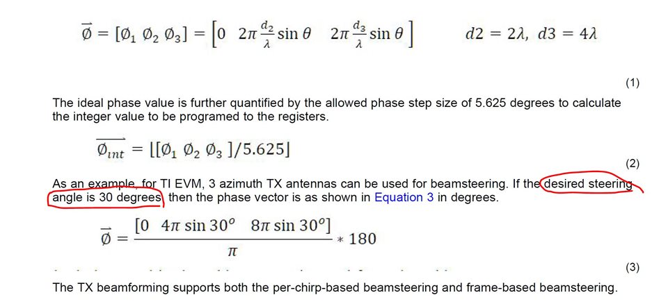
Figure1
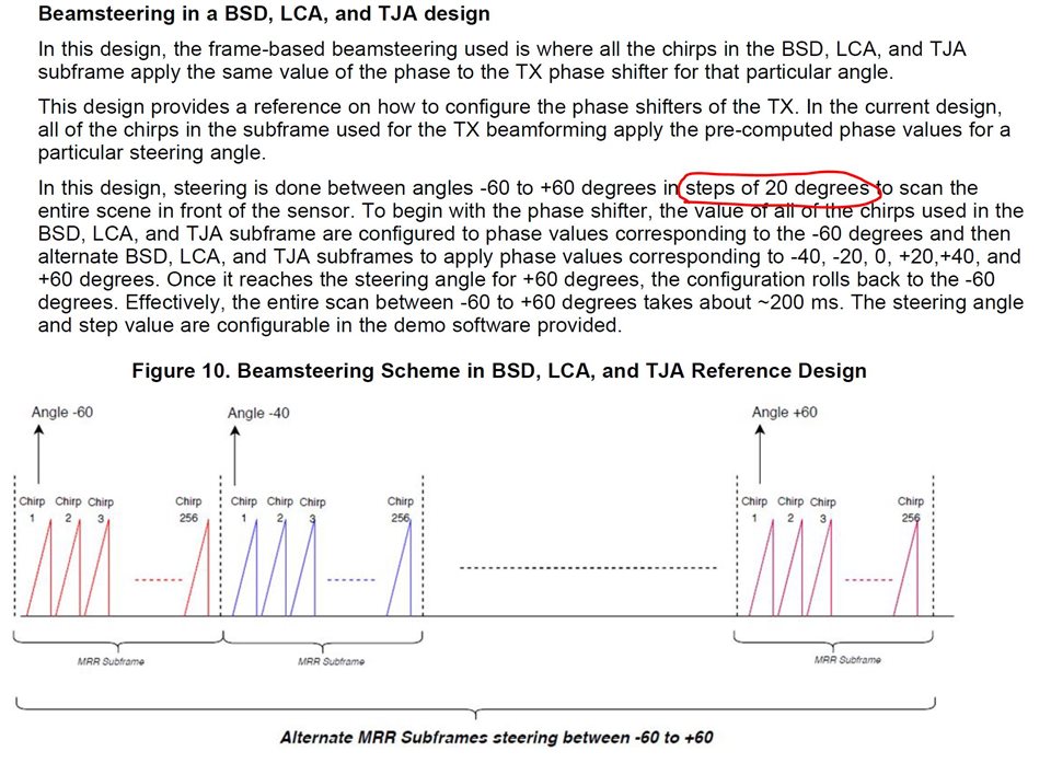
Figure2
Thanks,
Mostafa
