This thread has been locked.

If you have a related question, please click the "Ask a related question" button in the top right corner. The newly created question will be automatically linked to this question.

AWR2243: CSI Issue

Part Number: AWR2243
Other Parts Discussed in Thread: MMWCAS-RF-EVM

Hello,

We are having some issues interfacing a custom 4 x AWR2243 cascade board (based on the MMWCAS-RF-EVM board) with an Nvidia Jetson TX2 carrier board. We are using an Adaptor Board between the cascade board (which uses the same board-to-board connectors as the MMWCAS-RF-EVM board) and the TX2 carrier board - we have I-Pex connectors/micro-coax cables that we use to connect the CSI signals from the Adaptor board onto the TX2 carrier board.

We have separate buck and buck-boost dc/dc converters on the Adaptor board to power the cascade board at 5 V and TX2 board at 20 V, with an enable for the buck dc/dc converter used to ensure that the TX2 board is powered up first as we found that if we don't do this we cannot successfully program the AWR2243 chips using the SPI interface. 

The issue we are having is that the radar chips are shorting out when the I-Pex CSI cables are connected between the boards – the 1.8 V voltage rail on the AWR2243 chips is shorting out (I believe this powers the CSI section of the chip) and the 5 V input rail to the cascade board shorts out. Do you know what could be happening?

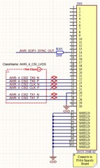
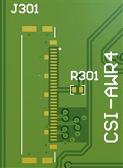
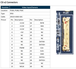
I've added schematic/layout below for one of the output CSI connectors on the Adaptor Board (top, for AWR2243 chip 4, i.e. slave 3) versus the input connector on the TX2 carrier board (bottom). Note that some pins have been left N/C as the carrier board CSI connector is designed with cameras in mind, i.e. as we don’t need to supply power from the TX2 board over these connectors so the 3.3 V/5 V pins were left N/C, likewise with the I2C and PWR#/RSET# pins.


Thanks,

Peter.

  • Hi,

    I asked the HW team to review your question

    They will get back to you as soon as possible

    thank you

    Cesar

  • Hello Peter,

    So you have only the 6 CSI lines going across these connectors , no other signals at all? When you do not interface this connector the 2243 is operating fine and the current on the 1.8V rail is fine?

    If the above two points are correct, then can you measure the impedance between the CSI pins and Gnd without powering up the boards, but after connecting the cables/connectors.

    Regards,

    Vivek

  • Hi Vivek,

    Yes that's correct, it is just those 6 csi signals on each CSI connector and when we don't connect the associated cables between the boards the Awr2243 is fine, with normal current draw.

    I'm out of the office but will measure that impedance tomorrow, thanks. 

    Best regards,

    Peter. 

  • Thanks for the confirmation Peter. Will wait for the impedance measurement results.

    Regards,
    Vivek

  • Hi Vivek

    I Measured the impedance between the CSI pins and GND on the Adaptor PCB before RF PCB is connected but with CSI cables connected between the Adaptor PCB and Spacely PCB:

    • AWR_X_CSI2_TX0_N = > 2 Mohm
    • AWR_ X_CSI2_TX0_P = > 2 Mohm
    • AWR_ X_CSI2_TX1_N = 9.0 Kohm
    • AWR_X_CSI2_TX1_P = 4.51 Kohm
    • AWR_X_CSI2_CLK_N = > 2 Mohm
    • AWR_X_CSI2_CLK_P = > 2 Mohm

    I then measured the impedance between the CSI pins and GND on the RF PCB, with RF PCB connected into the Adaptor PCB through the board-to-board connectors, with CSI cables connected between the Adaptor PCB and Spacely PCB:

    • AWR_X_CSI2_TX0_N = 212 Kohm
    • AWR_ X_CSI2_TX0_P = 212 Kohm
    • AWR_ X_CSI2_TX1_N = 3.81 Kohm
    • AWR_X_CSI2_TX1_P = 1.6 Kohm
    • AWR_X_CSI2_CLK_N = 13.1 Kohm
    • AWR_X_CSI2_CLK_P = 12.7 Kohm

    Best regards,

    Peter.

  • Hi Vivek,

    Just wondering if you've had a chance to review my impedance measurements?

    I'm thinking whether some kind of ground loop effect could be occurring - we have a lot of cable connections between the Adaptor PCB and Spacely PCB, i.e. 2-core DC power cable, 20-pin Misc IO cable (SPI/I2C/UART), 20-pin GPIO cable, 4 x I-Pex CSI-2 micro-coaxial cables. I'm thinking whether it would be worthwhile to:

    1. At the Adaptor Board side tie the shields for the I-Pex CSI connectors to ground through one or more capacitors (that present a low impedance over required CSI bandwidth) to prevent any dc currents flowing through them. On the Connect Tech Spacely side they use a 10 Mohm resistor between the cable ground and board ground.
    2. Use low-capacitance TVS diodes on the CSI-2 lines to give added protection - on the Connect Tech Spacely side they use TVS diodes on the camera IO lines (I2C etc), which we don't use, but not on the CSI-2 lines.
    3. Could try grounding each board (RF PCB, Adaptor PCB, Spacely PCB) to a common ‘chassis ground’, i.e. our enclosure housing.

    What do you think?

    Best regards,

    Peter.

  • Hello Peter,

    The impedances look high enough and there is no short to Gnd. So it does not appear to be CSI lines shorting. Since you are mentioning about the supply shorting, it has to be some low impedance path.

    There seems to some other signal from the I Pex card that seems to be causing the issue. What about pin 14? 

    Regards,
    Vivek

  • Could there be a Gnd connection issue between the I Pex card and the PCB ground? For example if the PCB supply is connected to one earth and the I Pex gnd to another earth (not floating gnd) , there could be large voltage difference between the two GNDs.

    Regards,
    Vivek

  • The other signal line we have connected on pin 14 of each connector is isolated with a DNF resistor so this couldn't be causing the issue. I checked to see if there is a ground difference between the GNDs on each board and there isn't, they're both at the same voltage.

    I checked with a multimeter what the voltage is on each of the CSI pins on the Adaptor PCB, with the Connect Tech Spacely PCB powered up but the RF PCB not connected:

    • AWR_X_CSI2_TX0_N = 0 V
    • AWR_ X_CSI2_TX0_P = 0 V
    • AWR_ X_CSI2_TX1_N = 4.95 V
    • AWR_X_CSI2_TX1_P = 3.28 V
    • AWR_X_CSI2_CLK_N = 0 V
    • AWR_X_CSI2_CLK_P = 0 V

    The voltage on the TX1 data pins is strange and could explain what's happening I guess given that AWR2243 would have absolute maximum rating on these pins of 2 V I think? Will check if these pins are correctly assigned on the Jetson TX2 side.

  • I know what the issue is now - the pin numbering is reversed at each side of the connector, i.e. what is called pin 1 at Spacely board side is what I call pin 30 on other side, hence why 3.3 V / 5 V are appearing on the DATA1 N/P connector pins.