Hi Sir,
I have some queries as below.
Can you help me to verify them?
Which wave is processed by FT?
Also, please tell me the difference between Range-FFT and Doopler-FFT and which wave to use?
Waiting your clarification.
Thanks.
Regards,
This thread has been locked.
If you have a related question, please click the "Ask a related question" button in the top right corner. The newly created question will be automatically linked to this question.
Hi Sir,
I have some queries as below.
Can you help me to verify them?
Which wave is processed by FT?
Also, please tell me the difference between Range-FFT and Doopler-FFT and which wave to use?
Waiting your clarification.
Thanks.
Regards,
Hello,
Range and Doppler FFT refers to 1D and 2D FFT for estimation of Range and velocity for the objects captured by the mmWave sensor.
These are the terms which are widely used across and not specific to TI Radar devices.
For starters, you could refer to the mmWave training series which explains in detail about the two computed FFTs :
https://training.ti.com/mmwave-training-series
The fundamentals of millimeter wave radar sensors (Rev. A)
Hope this helps you get started.
Regards,
Ishita
Hi Ishita,
Thank you for your reply.
BTW, can you share me which company made the mixer used in AWR 1843 boost?
Regards,
Hello Frank,
Sorry for the delay.
What is the mixer you're referring to here?
Is it the mixer in the RX chain? It's designed by TI, that's internally within the device and not the boost EVM.
Regards,
Ishita
HI Ishita,
Thank you.
it's Ok for the mixer, I am in a puzzle about datasheet, Can you explain it?
The sampling rate of A2D in RF specification of page 30 is 25Mbps and A2D resolution is 10MHz.
On the other side, the ADC sample rate of page 64 is 625ksps and the resolution is 10bits.
What's the difference?
Thanks.
Hello Frank,
These are two different parts you referring to here.
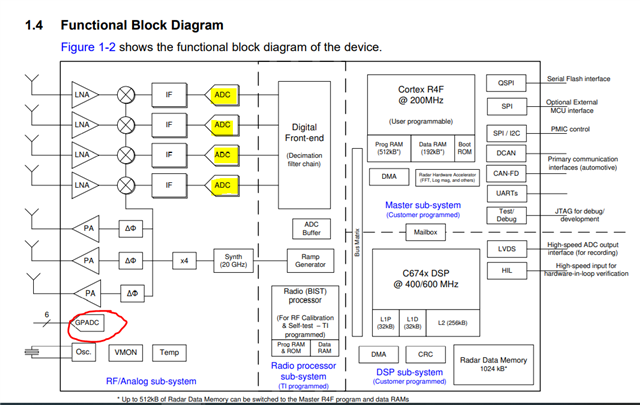
If you refer to the device block diagram in the datasheet (i.e. Figure 1-2) as seen below :

1. The highlighted components in yellow correspond to the ADCs in the receiver chain for sampling the data coming from receivers. The specifications in the RF Spec table correspond to this ADC
2. Now coming to Section 6.4.1 in the datasheet, it corresponds to the GPADC (highlighted in red) available for user application for external voltage monitoring purposes.
Hope this makes sense now.
Regards,
Ishita