This thread has been locked.

If you have a related question, please click the "Ask a related question" button in the top right corner. The newly created question will be automatically linked to this question.

TUSS4470: Custom Board Design for TUSS4470 - Underwater Distance Measurements - Noise Issues

Part Number: TUSS4470

Hi,
Following on from my previous posts regarding the evaluation of the TUSS470 sensor for underwater distance sensing applications.
I made an evaluation setup using the STM32L433RET connected to the development board BOOSTXL-TUSS4470, after lots of hours spent on the development everything works properly and very reliable measurements, sampling works on both by connecting a 24V high voltage source and using 5V.
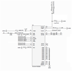
I designed a board based on STM32L433CB, and TUSS4470 (schematics attached below).
I have serious problems measuring at 1MHz, see screenshots below.

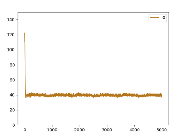
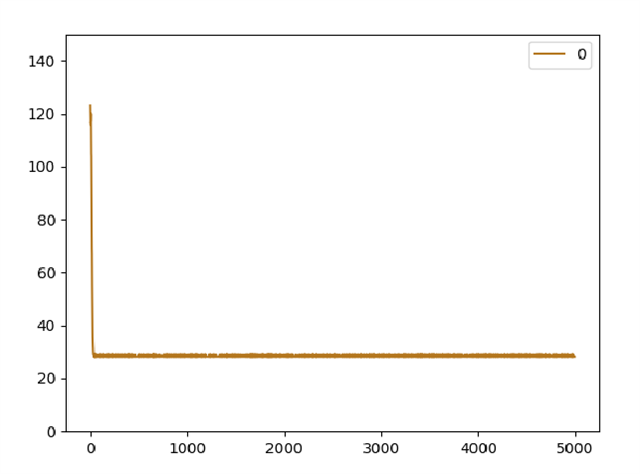
ADC is configured to sample at 32MHz, seen on the image the raw sampling through Vout pin processed by the ST-MCU.
I assume that the issues are related to FLT, INN capacitors, but I couldn't find any configuration where I can have similar results to those ones on the external BOOSTXL-TUSS4470 setup.
I'd love to have any idea about the design and how we can improve it and achieve better results using our custom-designed board.
TUSS4470 Schematics - 
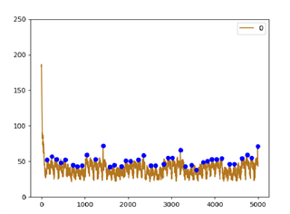
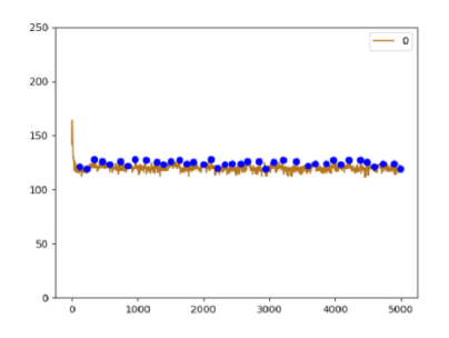
Reference Taken From STM32L446RET and BOOSTXL-TUSS4470 (1MHz Transducer) - 
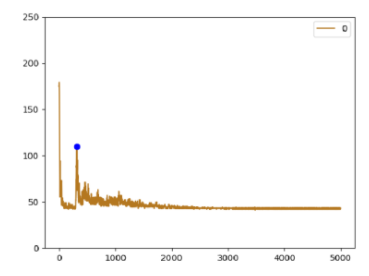
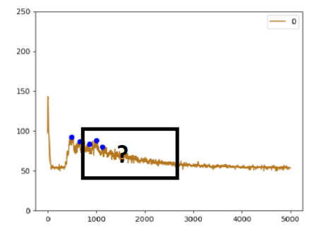
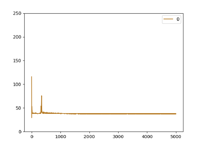
Custom board(1MHz Transducer) capacitors(CINN and FLT) as Noted on Datasheet and Schematics Above -
Any help would be greatly appreciated.
Thanks,
Itamar
  • Hello Itamar,

    It is possible that it could be the CINN and FLT capacitors, although those capacitor values might have worked perfectly on the BOOSTXL-TUSS4470 its possible the new custom board might be sensitive to these values. I calculated what should be the correct values these using the formulas found on pg. 31 of the datasheet and got smaller values ~600pF for C_FLT and ~4.2nF for C_INN. They might not be perfect but maybe a good starting point for reducing the noise.

    What I believe may be the main issue though is that I do not see any separation of the grounds in the schematic. Section 10 of the datasheet contains layout guidelines where it mentions (top bullet) that separating the ground types is key to reducing noise at the AFE:

    The list does contain other guidelines that could be part of the problem. Not sure if you have taken a look at this before but I hope this helps!

    Best,

    Isaac

  • Hi Isaac,

    Thanks for your reply. I also thought that would be the issue so I made another setup to eliminate the concern.

    I took the custom board instead of soldering the TUSS4470, I wired it to external BOOSTXL-TUSS4470. Results are similar to the ones noted above. 

    Clearly the capacitors I mentioned affect the result in such a setup even on the external BOOSTXL. But this setup actually rules out the possibility that this is an issue on the TUSS4470 side, but rather a ground noise affecting the ADC, VOUT in our case.

    I tried to supply power to the custom board both through the onboard DCDC TPS7B6933QDCYRQ1, and directly through the regulated power supply of the properly working ST setup, the results were the same.

    Thanks.

  • Hello Itamar,

    Just to be clear, this second setup that you did took the ADC that you are using on your custom board and paired it with the BOOSTXLTUSS4470 portion of the board and you sampled directly from that and the noise was still present?

    But if that is the case then I believe it definitely could be ground noise affecting the ADC values. That or not enough capacitance at for C_FLT, I tested today with almost no capacitance and the noise floor did rise up but it looked different from the plot that you provided.

    Have you tried changing the capacitor values on your custom board yet?

    Best,

    Isaac

  • Hello Isaac, 
    Without jumping straight to conclusions, I think that in the transition from the ST development board to the customized board, I had an issue with the SPI protocol implementation, which caused the component to not configure properly.
    On an open-air setup, it seems that it eliminates the ground noise, probably because of the internal HPF configured by the SPI, I will check it underwater in the next few days and update.


    But if that is the case then I believe it definitely could be ground noise affecting the ADC values. That or not enough capacitance at for C_FLT, I tested today with almost no capacitance and the noise floor did rise up but it looked different from the plot that you provided.

    Just for my general knowledge, CINN should remain according to the datasheet calculation of ~4.2nF, and FLT is the capacitor should be changed according to internal impedance due to my design?

    Thanks, 

    Itamar

  • Hey Itamar,

    That is correct, it seems like FLT capacitor needs to be optimized for your setup with a different trace impedance (internal impedance of the device should be approximately the same across devices) due to the board change and even across different applications since the transducer frequency might change. According to the datasheet this capacitor can change the response time as well as the peak-to-peak voltage of V_OUT. You can read this on page 20 of the data sheet.

    Best,

    Isaac

  • Hello Isaac,

    I did several tests over the last couple of days, I am getting unstable results on all options.
    Currently, I have three different setups:
    * STM32L433RE(Dev Board) and BOOSTXL-TUSS470.
    * STM32L433CB(Custom Board) and External BOOSTXL-TUSS470.
    * STM32L433CB(Custom Board) and Internal TUSS4470.
    Results from all three setups are now identical although the 3rd option could be a bit better using capacitor changing.
    All three systems were tested under two different input configuration:
    * Lipo-7s battery (~26V).
    * ACDC power adapter (24V).
    Using the battery as input, results are stable:
    Additionally, somehow on both custom setups, I get the following result:
    Using the second option, all three setups are barely usable, when the transducer is placed outside of the water the baseline is flat without any noise. When placing the transducer in water, the TUSS4470 baseline raises and gets very noisy:
    I succeed in filtering out the signal using the internal HPF/BPF configurations, capacitors changing which causes the baseline to be more stable, but there is no way to detect the returned echo on such signal (signal is expected to be the same as the first image).
    Any idea/thoughts? 
    Thanks.
    Itamar
  • Hey Itamar,

    Was this setup using the STM32L433RE(Dev Board) and BOOSTXL-TUSS470?

    Using the battery as input, results are stable:

    And the ones using the custom STM32L433RE board but with either the BOOSTXL-TUSS4470 or the one placed on your board you are getting these similar results correct?


    Is the transducer you are using rated for use in water?

    Best,

    Isaac

  • Hey Isaac,

    Was this setup using the STM32L433RE(Dev Board) and BOOSTXL-TUSS470?

    Yes.

    And the ones using the custom STM32L433RE board but with either the BOOSTXL-TUSS4470 or the one placed on your board you are getting these similar results correct?

    Yes. That's correct.

    I did this test to eliminate the option that the noise was only on my layout, results are the same on both setups.

    Is the transducer you are using rated for use in water?

    Yes, 100% sure.

    Thanks for your help.

  • Hey Itamar,

    Awesome thank you for the clarification. From the looks of this it looks like the problem might exists on the STM32L433RE on your custom board. The only usable reading you were able to get was on the development board with the BOOSTXL-TUSS4470. The way we might be able to prove this is if you can try to do a reading using the STM32L433RE development board and capture a reading using the TUSS4470 on your custom board. Not sure if this would be possible with your setup but if this is possible it  would eliminate the notion that there is something that needs to be changed on your TUSS4470 setup or not.

    Best,

    Isaac

  • Hi Isaac,

    Results are much better with a slitghly different registers configuration. My customized board gives great results operating on 24V battery as power source:  
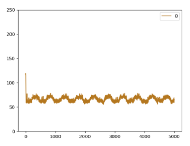
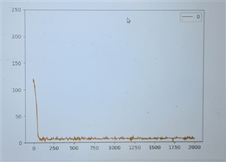
When i power the board using power supply from wall charger (24 VDC), i get the following results:
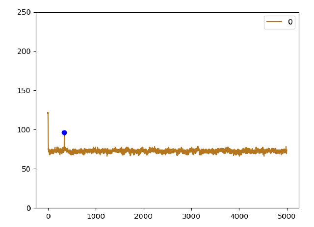
     I assume that if I apply a proper filtering on the power input i will have relatively good results.
    On the next revision, I will improve the ground isolation as suggested on the datasheet.
    Thanks for the help!
    I will update here regarding to the results.
  • Hello Itamar,

    That definitely seems to be the source of the problem here. Do not forget that there is also a power supply recommendations section to the datasheet that indicates some tips on how to avoid the additional noise on VOUT. You may find it on section 9 of the datasheet linked here. I hope this fixes the issue best of luck!

    Best,

    Isaac

  • Hi Isaac, 

    The strange behavior of the boards continues, when touching the transducer the 1MHz transducer with my hand in the open air, which I assume is the closest to being inside of a pool, there are completely different behaviors when operating under the battery and under power supply (AD-DC).
    It happens on both BOOSTXL-TUSS4470 and my customized board.

    Power Supply (24V):

    Battery (24V):

    Any idea what can cause this issue?

    Thanks.

  • Hello Itamar,

    When you touch the transducer with your hand what happens exactly? Are you seeing a rise in noise floor from the power supply vs the battery? I do not have much suggestions for the issue since I do not have plots when your has is not in the way, if you could provide some more info and plots that should be helpful.

    Best,

    Isaac