This thread has been locked.

If you have a related question, please click the "Ask a related question" button in the top right corner. The newly created question will be automatically linked to this question.

PGA900: Cann't run PGA900 on my own board

Part Number: PGA900
Other Parts Discussed in Thread: PGA300

I have OTP a PGA900 and tested it on EVM.

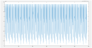
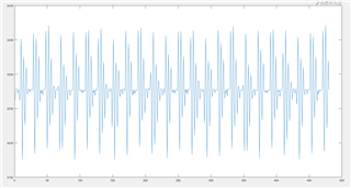
In my code, I only use the PADC channel of PGA900 and output by UART.

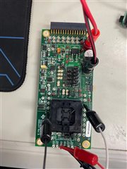
This is my connection of EVM, and in this situation,as I power on EVM, I can get UART output from MISO.

And then I replace this pga900 from EVM on my own pcb.But i couldn't get UART output while power on my pcb.

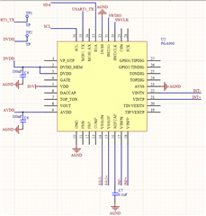
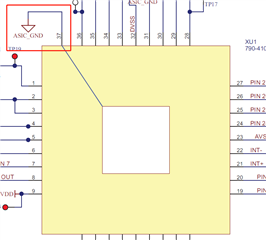
I designed my pcb reference from EVM users' guide like below.

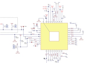
Because I only use PADC and UART, some pin i disconnet.Here is my pcb.

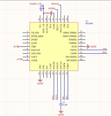
Now I am wondering whether I miss some pin to connect as I want to run a otped pga900 on my pcb.

  • Hello,

    The main issue is that DVDD_MEM (pin 2) is left floating. This pin powers the EEPROM and OTP memory, and must be connected to the DVDD pin. I also recommend tying the AVDD and DVDD (+DVDD_MEM) pins to ground through a 100nF capacitor close to the PGA900 device. Typically you would also use a decoupling capacitor at the VDD input as well,  but it can be a much smaller capacitor in the case where you intend to use OWI communication since extra capacitance can affect the edges of the OWI signals. When using OWI a 10nF capacitor is sufficient, but if you do not use OWI 100nF would work well.

    Regards,

    Scott

  • Hello Scott, I changed my PCB design as your advise.After that i can get uart output in my PCB but it seems didn't work well.

    For my PCB ,the voltage input is 50mv DC generated by a waveform generator.And i checked the powre for pga900, the DC 5v is generated by a LDO that should be steady.The pga900 on my pcb has been OTPed and I have verifyed and it worked well on EVM as I power on EVM it can output uartdata expectedly.The otped pga900 is configured as UART output, 5 gain on P channel and 16bit ADC.

    I receive my uart output and do curve plotting in matlab.

    This is my PCB outout plotting.It change acutely unexpectedly.

    Then I put the same pga900 on EVM,for the same input voltage,and do curve plotting in matlab again.This time it worked well.

    So i wonder why the same OTPed pga900 worked differently on my pcb and EVM.Is there still something I missed in my PCB design?

  • Hi Gibson,

    I also recommend grounding the GATE pin if you are not using it. My apologies for leaving that out. I would recommend checking against the schematic for the EVM with respect to the unused input pins. The output pins are less essential and can be left floating.


    Regards,

    Scott

  • There are a few input pins like COMP pin13,CSN pin29,FBN pin11,FBP pin12 and etc some inpu pins I didn't use.Should I also conenct them like schematic for the EVM?

  • I connect GATE pin to AGND, but this issue didn't get solved.Could you give me more help?

    This time the output data didn't change sharply like befor.This time the output changed from -2000 to 5000 that is better than make GATE pin floating.
    But in EVM it changed from 3200 to 3350, the resoult on EVM is more accurately.And I wonder the reason and improve the same pga900's behavior on my own PCB.

  • Hello,Scott.I'm waiting for you reply,thx

  • Hello Gibson,

    Can you monitor the pressure inputs on your PCB with an oscilloscope? It would be good to confirm if this is noise on the inputs or if there is something going wrong internally due to a potential incorrect connection.

    I also recommend reviewing this PGA300 reference design (https://www.ti.com/tool/TIDA-00788) for some example layout and schematic connections. The analog components are identical in the PGA300, but it does not include the M0 microcontroller.


    Regards,
    Scott

  • Hello,Scott.

    The pressure input was generated by waveform generator, and I monitor it on my PCB with an oscilloscope is no noise.

    So i'm still confused how to solve this issue?

  • I didn't connect PIN37 to AGND,does this can cause my issue?

  • Hello,

    The powerpad is helpful in stabilizing thermal performance which in turn affects the performance of the rest of the device, including the sigma delta ADCs. This could be a potential cause for the increased noise you are seeing.


    Regards,

    Scott 

  • Hello,Scott.

    I want to check pga900's PADC, and I connect a sinusoidal wave (which is generated by waveform generator, 1Hz and -300mv to 300 mv)to VINPP and VINPN.But the result was not good.

    Should I add a RC filter to VINPP and VINPN? I am wondering what value of resistance and capacitance should I pick?

  • Hello, 

    The sine wave will need to be biased properly to avoid violating the recommended operating conditions for the PGAIN inputs. What voltage is it centered at?

    An RC filter can certainly help limit high frequency noise that is affecting your signal. The values you choose will depend mainly on the expected input signal. For a very low frequency signal like the one you are testing with, you can have a quite low cutoff frequency. I would start around 15khz with a 1kohm resistor and a 10nF capacitor for your RC.


    Regards,

    Scott