This thread has been locked.

If you have a related question, please click the "Ask a related question" button in the top right corner. The newly created question will be automatically linked to this question.

TUSS4470: Ringing reduction

Part Number: TUSS4470

Hello,

We made a design using the recommendations in the TUSS4470 datasheet but the ringing is too high. We use a ProWave 400EP14D ultrasound sensor which can both emit and detect.

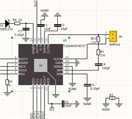
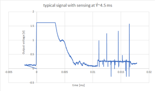
We use maximum amplifications as our signal is very weak. We use the analog output and make our own discrimination. However, the output is saturated up to ~3 ms and then decreases roughly linearly to 0 in another 3 ms. (in the above graph the signal is limited by the oscilloscope to 1.6V. We tried to change the number of pulses from 20 down to 8 without any change in the first peak. The excitation voltage is set to 20V. On the above graph you can see the signal coming back from the object just below 5 ms. We would like to be able to detect objects at ~25-30 cm which means below 2 ms. How can we improve our design?

  • Carl,

    Thanks for reaching out with your question.  A useful application note that discusses this subject is here:

    https://www.ti.com/lit/an/slaa907c/slaa907c.pdf

    In section 2.8, it discusses a variety of options that might be useful in shortening the ring-down period.  One option is to use a higher frequency transducer.  This, however, may limit the total sensing range of your solution, since higher frequency pulses will decay faster.  Another alternative, which you have started to try is to reduce the number of pulses.  You might experiment with less than 8, but if you do not receive a strong enough echo signal back this might not be a good alternative.  A third choice is to reduce the drive voltage or possibly set the VDRV current setting lower.  After these options, one further option which you might attempt is to adjust the output filter.  Currently, it appears that you have a 220 Ohm damping resistor in parallel with your transducer.  You might try temporarily inserting a potentiometer here and adjusting this resistance to see if you can find a better balance on the ring down time for your application.

    Thanks,

    Scott

  • Dear Scott,

    Thank you for your fast reply. The application note and the list of sensors in it are very interesting.

    I will upload the ringing of the sensor. I was convinced until yesterday that this is the problem, but I have big doubts. We changed the number of pulses from 4 up to 20 and could not see any change in the first envelope. Indeed, the burst lasts few hundred us, the ringing seen on the oscilloscope another 200 us but the peak signal on the output is nearly 6 ms. I wonder if the LNA does not get saturated with the peak signal or the filtering capacitor is too big? We are going to verify these two ideas. I will also follow the recommendation to reduce the drive voltage from the current max value to maybe 10V. We played with the damping resistor at the beginning of our project. This is how we got to the 220 Ohm. This is already quite small.

    Could one of the filter settings enlarge the signal to the extent we see?

    Our initial peak spreads much more than the one in your datasheet.

    We also tried two completely different sensors: one symetrical and the other asymetrical. They are different in size, in sensitivity but the initial envelope curve was the same for both. We even implemented an algorithm to substract a slope from the signal to remove a large part of the peak. It is efficient when the peak is small but we could not detect anything below ~3.5-4ms. The shape is very reproducible. We tested several TUS4470 and several sensors and the differences were on the scale of 5%.

    I appreciate very much your help.

  • Carl,

    It might be possible that the filter settings may have an impact.  Could you provide your device configuration so that I could look for anything out of sorts?

    Thanks,

    Scott

  • Dear Scott,

    We made a lot of testing on Friday. Indeed, the ringing is the issue. As it is decaying very slowly, 1st it was difficult to observe. We tried to change the Cflt value reducing it from 15nF to  2.2 nF. This was not a good idea as it only removed the filtering of the 40 kHz. We changed the number of pulses from 16 to 4. This helped reducing the saturation by ~0.5 ms. It went in the right direction but at the same time, the signal intensity became too weak.

    We then changed the different amplification options. As the signal to noise ratio due to the ringing is very bad, the amplification had no real effect.

    We also varied the damping resistor. Our original value between 220 and 360 Ohm seems to be the optimum.

    Finally, we tried to put a single pulse 180° out of phase after the 4 initial pulses. Unfortunately, the Piezo sensor is "too good" and although we reduced the oscillations intensity but now the decay was slower so the effect was very small. Probably, we would have to develop a special pulse which is just enough to absorb the oscillation energy. Should we try? Not very easy with your chip.

    Today, we received the evaluation board from ProWave. They use an adjusted transformer. The signal was beautiful. We could detect easily objects down to less than 25cm. Their drive method is also described by your datasheet (an external transformer pumps up the voltage on the sensor). I can understand that the signal is bigger because we have 140Vpp instead of 36Vpp but I cannot understand why the ringing is so small. We could do the same with the Tuss4470. However, I am afraid that we will have to adjust each driver to the correct impedance. Is there a way to go around the transformer technique? Maybe using an inductance? (We tried 10 mH in parallel with the sensor without any effect even if this would give ~40 kHz resonance frequency with the sensor)

    Here are the register values we set via the SPI:

    tuss_config_write(0x10,0x00);        // BPF_CONFIG_1
      tuss_config_write(0x12,0x82);        // DEV_CTRL_1
       tuss_config_write(0x13,0x46);        // DEV_CTRL_2 20V/V
       tuss_config_write(0x14,0x01);        // DEV_CTRL_3 IO_MODE=1
      tuss_config_write(0x16,0x0F);        // VDRV_CTRL
        tuss_config_write(0x17,0x10);        // ECHO_INT, level minimum 0.6V
        tuss_config_write(0x1A,SENSOR_PULSE);        // BURST_PULSE fix 16
        tuss_config_write(0x1B,0x40);        // TOF_CONFIG standby

    Best regards,

    Balázs (Carl's colleague)

  • It looks like you have the transducer frequency set to 40.64 kHz with a Q factor of 4, and this very closely matches the transducer specification 40 kHz +/- 1 kHz. 

    I did notice a few items that seemed inconsistent in the register settings:

    • Receiver dynamic range will be limited somewhat when you disable the last stage of the log amp in register 0x13.
    • You are also setting the IDRV current in register 0x16, but not enabling this feature in register 0x1A.
    •  VDRV is set to the maximum value.  Have you attempted to adjust this down at all?

    Does the Prowave module use the same transducer?  Can you provide more details how they have the device configured?  My expectation for the shorter ring down despite using a higher drive voltage is that they are able to use fewer bursts which limit the ringdown time.

    It also looks like you are driving the device in Mode 1 where the burst pulses are initiated by the falling edge of IO2.  What is the timing of this clock?  Do your IO1&IO2 follow the pattern in figure 16?

    Thanks,

    Scott