Other Parts Discussed in Thread: TUSS4470, MSP430F5529, ENERGIA
Hello,
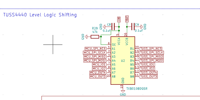
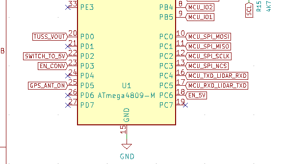
I have been breaking my head over why TUSS4440 is not exciting the transducer, I am not able to spot the issue. The schematics look the following:
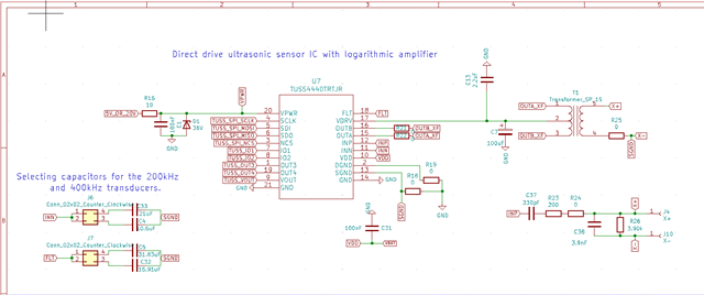
I am trying to perform a simple TOF measurement, and convert it to CM based on the examples provided by TI and also here. The frequency on the IO2 pin is set to 200Khz which shows up on the osciloscope, the SPI settings are also default ones.
The code:
// code sources:// A : msp430_driverlib_2_91_13_01\examples\MSP430F5xx_6xx\usci_a_spi/usci_a_spi_ex1_master.c// B : TUSS4470 examples\examples\VOUT_ADC_Processing\TUSS44x0_ultrasonic.cpp// C : msp430_driverlib_2_91_13_01\examples\MSP430F5xx_6xx\adc12_a/adc12_a_ex5_repeatedSingle.c
#include "stdio.h"#include <stdbool.h>#include <stdint.h>#include <avr/sleep.h>#include <avr/delay.h>#define F_CPU 5000000UL// Prototypesunsigned int BitShiftCombine( unsigned char x_high, unsigned char x_low);void executeTOFandSample();void initializeTUSS4440();void init_GPIO();void initTimer();void initClocks();void initTUSS4470();void initSPI();void initADC12(); void initDMA();uint8_t parity16(unsigned int ino);void sampleLoop();uint8_t * tuss44x0_regAddParity(uint8_t addr, uint8_t data);uint8_t tuss44x0_parity(uint8_t * spi16Val);void writeRegTUSS4470 (uint8_t address, uint8_t value);
// SPI Variables#define SPICLK 500000uint8_t SPIInitReturnValue = 0;
// Clock/UCS variablesuint16_t NMIstatus;#define LF_CRYSTAL_FREQUENCY_IN_HZ 32768#define HF_CRYSTAL_FREQUENCY_IN_HZ 4000000#define MCLK_DESIRED_FREQUENCY 4000000 // 4 MHz#define MCLK_FLLREF_RATIO MCLK_DESIRED_FREQUENCY / UCS_REFOCLK_FREQUENCY uint32_t myACLK = 0;uint32_t mySMCLK = 0;uint32_t myMCLK = 0;
// TOF Variablesuint8_t sampleSetLoopCount = 0;bool samplingActive = false;
// ADC variables#define ADC12_Num_of_Indexes 20#define ADC12_Num_of_Results 125volatile uint8_t ADC12_results_index1 = 0;volatile uint8_t ADC12_results_index2 = 0;int ADCValuesCounterResults = 0;int ADCValuesCounterIndex = 0;volatile uint16_t ADC12_results[ADC12_Num_of_Indexes][ADC12_Num_of_Results] = {};
// DMA variables#define ANALOG_DMA_CHANNEL DMA_CHANNEL_0#define ANALOG_INPUT ADC12_A_INPUT_A5#define ANALOG_MEMORY ADC12_A_MEMORY_0
unsigned int speedOfSound = 0x0157; // default speed of sound through air at room temperature is 343 m/s
void sampleLoop(){
}
//// Initialization /////
void initializeTUSS4440() {
TCB2_Initialize(); TUSS4440_Initialize(); // initialize SPI communication for ATmega4809 -> TUSS4470 // initTimer(); // initialize timer for 1MHz pulse // initSPI(); // initialize SPI communication for MSP430 -> TUSS4470 // initADC12(); // initialize ADC12 A/D converter in MSP430F5529 initTUSS4470(); // initialize/configure TUSS4470}
//// Timer Initialization ////// PWM timer - generate 1MHz transducer pulses - SMCLK must be 4 MHz
//// ADC Initialization ////// code source: C
void initADC12() { // ADC clock source is configured as SMCLK // SMCLK and MCLK = 4MHZ // Calculate minimum required sample time // calculation source: MSP430 User guide section 28.2.5.3 'Sample Timing Considerations' // The resistance of the source RS and RI affect tsample. The following equation can be used to calculate the // minimum sampling time tsample for a n-bit conversion, where n equals the bits of resolution: // t.sample > (RS + RI) * ln(2n+1) * CI + 800 ns // Substituting the values for RI and CI given above, the equation becomes: // t.sample > (RS + 1.8 KOhm) * ln(2n+1) * 25 pF + 800 ns // For example, for 12-bit resolution, if RS is 10 KOhm, t.sample must be greater than 3.46 uS. // using measurement of 4.2 KOhms output resistance of TUSS4470 // sample > (4.2 Kohm + 1.8 KOhm) * ln(2 ^ (12 + 1)) * 25 + 800ns // sample > 2.151 us // minimum sample time = 2.15 uS // if ADC clock = 4MHZ, 1 cycle = 0.25 uS, a minimum of 9 cycles (2.25 uS) is required to meet minimum sample time of 2.15 us (16 cycles or 3.2 uS is closest driverlib option)
// configure REF (reference voltage) module
}
//// SPI Initialization ////
// code source: A
void initSPI() {
}
//// TUSS4470 Initialization ////
void initTUSS4470(){ // recommended TUSS4470 register settings from INDUS_REG_USER_MEMSPACE_447-StemincTDCXDCR_Optimized.txt // e2e.ti.com/.../927400
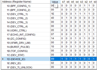
writeRegTUSS4470(0x10 ,0x5F); // (BPF_CONFIG_1) writeRegTUSS4470(0x11 ,0x00); // (BPF_CONFIG_2) writeRegTUSS4470(0x12 ,0x1C); // (DEV_CTRL_1) writeRegTUSS4470(0x13 ,0xC1); // DEV_CTRL_2) writeRegTUSS4470(0x14 ,0x00); // (DEV_CTRL_3) writeRegTUSS4470(0x15 ,0x00); // (DEV_CTRL_4) writeRegTUSS4470(0x16 ,0x40); // (VDRV_CTRL) writeRegTUSS4470(0x17 ,0x07); // (ECHO_INT_CONFIG) writeRegTUSS4470(0x18 ,0x14); // (ZC_CONFIG) writeRegTUSS4470(0x19 ,0x00); // (XFMR_DRV_LIM) writeRegTUSS4470(0x1A ,0x08); // (BURST_PULSE) writeRegTUSS4470(0x1B ,0x02); // (TOF_CONFIG) writeRegTUSS4470(0x1C ,0x08); // (DEV_STAT) writeRegTUSS4470(0x1D ,0xB9); // (DEVICE_ID) writeRegTUSS4470(0x1E ,0x02); // (REV_ID) writeRegTUSS4470(0x1F ,0x00); // (DEV_TI_UNLOCK)}
typedef struct { // hardware stuff that controls SPI mode // hardware stuff that controls SPI baud rate uint8_t CTRLAvalue; uint8_t CTRLBvalue;} spi0_configuration_t;// code source: B//// write register values to TUSS4470 over SPI bus ////void writeRegTUSS4470 (uint8_t address, uint8_t value) { uint8_t *regValPtr; uint8_t tuss4470regWriteArray[2];
regValPtr = tuss44x0_regAddParity(address, value); tuss4470regWriteArray[0] = *regValPtr; tuss4470regWriteArray[1] = *(regValPtr + 1); // increment pointer 1 byte
//Enable SPI module TUSS4440_Initialize(); TUSS4440_Enable(); spi0_configuration_t t; t.CTRLAvalue = 0; t.CTRLBvalue = 16000; TUSS4440_Open(t); //Wait for slave to initialize _delay_ms(100);
//USCI_B0 TX buffer ready? clientSelect(); TUSS4440_WriteByte(tuss4470regWriteArray[0]); TUSS4440_WriteByte(tuss4470regWriteArray[1]); clientDeselect();}
// code source: B//// Execute Time of Flight and Sample ////typedef uint16_t adc_result_t;/* Analog Channel Selection Bits select */
/** Datatype for the result of the ADC conversion */typedef uint16_t adc_result_t;
void executeTOFandSample() {
writeRegTUSS4470(0x1B, 0x00); // TOF_CONFIG's CMD_TRIGGER to 0 writeRegTUSS4470(0x1B, 0x01); // TOF_CONFIG's CMD_TRIGGER to 1 (enable burst mode) adc_result_t res; ADC_MUXPOS_t channel; channel = ADC_MUXPOS_AIN0_gc; //channel; // ADC12 sample and convert TUSS_ANALOG_INPUT_StartConversion(channel); TCB2_EnableCaptInterrupt();
_delay_ms(10); //res = TUSS_ANALOG_INPUT_GetConversion(channel);
// P8OUT |= BIT2; // set pin 8.2 high - for oscilloscope timing tests //__delay_cycles(40); // 40 cycle delay produces ~ 12 to 14 pulses at 1MHz if SMCLK = 4 MHz TCB2_DisableCaptInterrupt(); writeRegTUSS4470(0x1B, 0x00); // TOF_CONFIG's CMD_TRIGGER to 0 (disable burst mode)
}
double tofToDistance(unsigned long tofTime){ return (tofTime * (speedOfSound * 0.5)) * 0.001; }
// code source: B/*------------------------------------------------- tuss44x0_regAddParity ----- | Function tuss44x0_regAddParity | | Purpose: Modify addr byte, Calculate Parity bit and return array pointer. | | Parameters: | addr (IN) -- valid register address byte between 0x10 to 0x1E | data (IN) -- valid register data byte between 0x00 to 0xFF | | Returns: none *-------------------------------------------------------------------*/uint8_t * tuss44x0_regAddParity(uint8_t addr, uint8_t data){ uint8_t regByteArr[2]; regByteArr[0] = (addr & 0x3F) << 1; // shift addr to MSB position regByteArr[1] = data; // null data byte during read regByteArr[0] |= tuss44x0_parity(regByteArr); // apply parity bit return regByteArr;}
// code source: B/*------------------------------------------------- tuss44x0_parity ----- | Function tuss44x0_parity | | Purpose: Calculates odd parity bit for given SPI data. | | Parameters: | spi16Val (IN) -- 16 bit SPI data byte array | | Returns: byte representation of SPI data array element 0's LSB | containing calculated parity bit value *-------------------------------------------------------------------*/uint8_t tuss44x0_parity(uint8_t * spi16Val){ // SPI frame comprised of: 1 RW bit, 6 bits for the register address, 1 ODD parity bit for entire SPI frame, 8 bits for data return parity16(BitShiftCombine(spi16Val[0],spi16Val[1]));}
// code source: B/*------------------------------------------------- tuss44x0_parity ----- | Function tuss44x0_parity | | Purpose: Determines the number of ones in a given unsigned integer | to return odd parity bit result. | | Parameters: | ino (IN) -- 16 bit unsigned integer | Returns: parity bit value *-------------------------------------------------------------------*/uint8_t parity16(unsigned int ino){ int i = 0; uint8_t noofones = 0; for(i = 0; i < 16; i++) { if(((ino>>i) & 1) == 1) { noofones++; } } // if remainder of one, add one to parity bit field return ((noofones+1) % 2);}
// code source: B/*------------------------------------------------- BitShiftCombine ----- | Function BitShiftCombine | | Purpose: Combines two byte values into a single unsigned integer value. | | Parameters: | x_high (IN) -- MSB input byte | x_low (IN) -- LSB input byte | | Returns: unsigned integer of combined MSB and LSB bytes *-------------------------------------------------------------------*/unsigned int BitShiftCombine( unsigned char x_high, unsigned char x_low){ unsigned int combined; combined = x_high; // send x_high to rightmost 8 bits combined = combined<<8; // shift x_high over to leftmost 8 bits combined |= x_low; // logical OR keeps x_high intact in combined and fills in rightmost 8 bits return combined;}
Any help is greatly appreciated!