This thread has been locked.

If you have a related question, please click the "Ask a related question" button in the top right corner. The newly created question will be automatically linked to this question.

PGA460-Q1: PGA460TPWQ1

Part Number: PGA460-Q1
Other Parts Discussed in Thread: PGA460, MSP430F5529

We are using the PGA460 in our design for a litter bin waste level sensor and have decided to produce an early prototype using a Mikroe 3302 board that ulilizes the PGA460. We are struggling with the parameter settings and are not getting any meaningful readings. We have checked the drive out from OUTA and OUTB through the transformer to the Ultrasonic sensor and are seeing a burst of about 50V-60V at the sensor pins. Do you have any recommended parameter settings and initial set up steps we can use to get us into the right ball-park?

  • Hello Conrad,

    The ideal PGA460 settings would vary depending on the selected transducer and the system. So it is difficult to say what are the optimal PGA460 settings for your board and application.

    We do, however, have example settings for the PGA460 EVM and its transducers. The following video series goes over examples on how to setup various settings for the PGA460 EVM:
    https://training.ti.com/pga460-ultrasonic-sensing-how-set-and-install-evm?context=1128182-1128152


    If you are not getting an echo response, I would first recommend looking at the transducer datasheet to make sure that you are using the appropriate PGA460 settings for the transducer related parameters, such as burst frequency, number of pulses, and drive current. I would also try probing the PGA460 INx pins to see if a response echo can be observed there.

    Best,

    Isaac

  • Hi Issac

    Thank you for your answer.

    We are using a Mikroe-3302 '2-Click' development board to develop our product.

    https://www.mikroe.com/ultrasonic-2-click

    I'm not sure what transducer is fitted but I am in the process of asking them.

    The plan is to do our first design steps using the Mikroe-3302 then track-up our oen PCB.

    From what I gather it is a 4Khz device.

    The transformer is a B78416A2232A003 https://www.tdk-electronics.tdk.com/inf/85/ds/B78416A2232A003.pdf

    The Mikroe 3302 circuit looks very similar to the TI PGA460PAM-EVM circuit so the transducer amy be the same if not very similar.

    https://download.mikroe.com/documents/add-on-boards/click/ultrasonic-2/ultrasonic-2-click-schematic-v100.pdf

    Kind regards

    Conrad

  • Hi Isaac

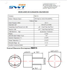
    I now have the data on the Ultrasonic Transducer fitted to the Mikroe-3302 '2-Click' development board we are using.

    The part number is USC14T/R - 40MPWA

    https://www.swt99.com/Ultrasonic-Sensor-14mm-40kHz-USC14T-R-40MPWA-pd214264.html

    I made a typo in my last reply, I put 4Khz where I should have put 40Khz.

    Kind regards

    Conrad

  • Hey Conrad,

    Thanks for the info.

    ;GRID_USER_MEMSPACE
    00 (USER_DATA1),00
    01 (USER_DATA2),00
    02 (USER_DATA3),00
    03 (USER_DATA4),00
    04 (USER_DATA5),00
    05 (USER_DATA6),00
    06 (USER_DATA7),00
    07 (USER_DATA8),00
    08 (USER_DATA9),00
    09 (USER_DATA10),00
    0A (USER_DATA11),00
    0B (USER_DATA12),00
    0C (USER_DATA13),00
    0D (USER_DATA14),00
    0E (USER_DATA15),00
    0F (USER_DATA16),00
    10 (USER_DATA17),00
    11 (USER_DATA18),00
    12 (USER_DATA19),00
    13 (USER_DATA20),00
    14 (TVGAIN0),88
    15 (TVGAIN1),88
    16 (TVGAIN2),88
    17 (TVGAIN3),82
    18 (TVGAIN4),08
    19 (TVGAIN5),20
    1A (TVGAIN6),80
    1B (INIT_GAIN),60
    1C (FREQUENCY),32
    1D (DEADTIME),00
    1E (PULSE_P1),05
    1F (PULSE_P2),12
    20 (CURR_LIM_P1),40
    21 (CURR_LIM_P2),7F
    22 (REC_LENGTH),8C
    23 (FREQ_DIAG),00
    24 (SAT_FDIAG_TH),EE
    25 (FVOLT_DEC),7C
    26 (DECPL_TEMP),0A
    27 (DSP_SCALE),00
    28 (TEMP_TRIM),00
    29 (P1_GAIN_CTRL),08
    2A (P2_GAIN_CTRL),00
    2B (EE_CRC),9B
    40 (EE_CNTRL),00
    41 (BPF_A2_MSB),85
    42 (BPF_A2_LSB),8D
    43 (BPF_A3_MSB),F9
    44 (BPF_A3_LSB),A5
    45 (BPF_B1_MSB),03
    46 (BPF_B1_LSB),2D
    47 (LPF_A2_MSB),7E
    48 (LPF_A2_LSB),67
    49 (LPF_B1_MSB),00
    4A (LPF_B1_LSB),CD
    4B (TEST_MUX),00
    4C (DEV_STAT0),80
    4D (DEV_STAT1),00
    5F (P1_THR_0),88
    60 (P1_THR_1),88
    61 (P1_THR_2),88
    62 (P1_THR_3),88
    63 (P1_THR_4),88
    64 (P1_THR_5),88
    65 (P1_THR_6),84
    66 (P1_THR_7),21
    67 (P1_THR_8),08
    68 (P1_THR_9),42
    69 (P1_THR_10),10
    6A (P1_THR_11),80
    6B (P1_THR_12),80
    6C (P1_THR_13),80
    6D (P1_THR_14),80
    6E (P1_THR_15),00
    6F (P2_THR_0),88
    70 (P2_THR_1),88
    71 (P2_THR_2),88
    72 (P2_THR_3),88
    73 (P2_THR_4),88
    74 (P2_THR_5),88
    75 (P2_THR_6),84
    76 (P2_THR_7),21
    77 (P2_THR_8),08
    78 (P2_THR_9),42
    79 (P2_THR_10),10
    7A (P2_THR_11),80
    7B (P2_THR_12),80
    7C (P2_THR_13),80
    7D (P2_THR_14),80
    7E (P2_THR_15),00
    7F (THR_CRC),28
    EOF
    

    I attached a text document as a starting point for PGA460 settings with a 40kHz transducer.

    Frequency - 40kHz

    Pulses Transmitted - 5 (should be higher if the distance is larger)

    Driver Current- 50mA (this is transducer dependent set it low since there is no spec on the datasheet provided)

    Record Length - 36.86ms (this can measure a little over 6m, can be configured to be less or more if needed)

    Digital Gain- x2

    LPF Cutoff- 2kHz

    BPF BW- 4kHz 

    The time varying gain is set to a set level here of 74.5dB and the threshold is set to a set value also with equal spacing. These usually require the most tuning depending on your application.

    The setup of these gain and threshold values depends on the distance you are typically measuring and what you are measuring. I usually recommend using the GUI during this stage because it helps in visualizing the settings and the echo behavior. If you are having issues you should be able to get an MSP430F5529 board to interface with the GUI and help with the setup. But I hope these settings help for now!

    Best,

    Isaac