This thread has been locked.

If you have a related question, please click the "Ask a related question" button in the top right corner. The newly created question will be automatically linked to this question.

IWR6843ISK: Steering Vector using BPM MIMO configuration for Azimuth and Elevation angle estimation

Part Number: IWR6843ISK

Hello,

 I am using DCA1000+IWR6843ISK+MMWAVEBOOST boards and mmwave studio to collect raw data.

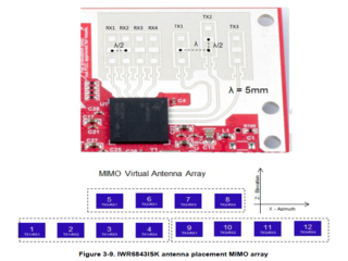
Radar Configuration : enabled 3 Tx and 4 Rx with BPM MIMO. So, 12 virtual antennas.

I am trying to calculate the Azimuth and Elevation angle using Barlett and MUSIC methods. To do that first need to make sure about the Steering vercor formula.

I have 2 questions,

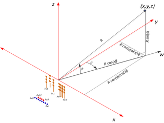
  1. According to my understanding The steering vector calculation should be like this,

   steeringVector =  e^(-1*pi*(dx*sin(azimuth)*cos(elevation) + dy*cos(azimuth)*cos(elevation)))  where, -60<=azimuth<=60 and -15<=elevation<=15,

  and      array_dx = [0  1/2  1  3/2  1  3/2  2  5/2  2  5/2  3  7/2];  // This is based on the ordering of below image. Just followed the oder of the virtual antennas in the image. 
              array_dy = [0  0  0  0  1/2  1/2  1/2  1/2  0  0  0  0];   // Same here, following the virtual antenna array position in the image below.

Is this correct?

  1. I am considering 12 virtual antennas to calculate this steering vector. Is it the correct way? Or should I consider only 8 vistual antennas which are no, [3,4,5,6,7,8,9,10]? Or something else? I am calculating based on these 2 images. The images are below.


I look forward to your reply.

Thank you.

Best regards,

Nazmul

  • HI, Nazmul:

    Please go through the SDK Doxygen documentation on AOA module and AOA 2D module. 

    1) AOA module

    file:///C:/ti/mmwave_sdk_03_05_00_04/packages/ti/datapath/dpc/dpu/aoaproc/docs/doxygen/html/index.html

    2) 2D AoA module 

    file:///C:/ti/mmwave_sdk_03_05_00_04/packages/ti/datapath/dpc/dpu/aoa2dproc/docs/doxygen/html/index.html

    For ISK module, the SDK demo is using the first method.  What you propose is the second method, the two dimensional spectrum calculation.   There is nothing wrong to use 2D spectrum for ISK module.  You can implement both and compare the performance.  

    You can check the code to verify your steering vector generation.  It may need to be doubled.  

    Best,

    Zigang

  • Hi Zigang,

    Thank you for sharing the information. 

    I modified the steering vector according to the docs you shared. But it does not work and the one I asked that does not work also. 

    According to the doc the steering vector should be,

    steeringVector(azimuth,elevation) =  e^(-1*pi*(dx*sin(azimuth)*cos(elevation) + dy*sin(elevation)))  where, -60<=azimuth<=60 and -15<=elevation<=15,

    Also modified the array index according to the document.

    array_dx = [0 1 2 3 2 3 4 5 4 5 6 7]; 
    array_dy = [1 1 1 1 0 0 0 0 1 1 1 1];

    I am not sure why this is not working. The azimuth result is deviated and elevation is showing either -15 or +15 degree.

    Do you think this is correct?

    For this rectangular array antennas I checked some papers, which suggest the steering vector that I asked you first. 

    I checked the code in that folder, but I did not find where the 2d steering vector is implemented.

    My point is, it should be implemented/worked according to the theory.

    Where is the mistake?

    Best regards,

    Nazmul

  • Hi, Nazmul:

    I would suggest you to test our code and if it works then compare the difference between your code and the demo code. 

    I won't able to debug for you. Good luck!

    Best,

    Zigang

  • Hi Zigang,

    What I asked in the post, that is about the right steering vector, You have already answered me. At least I have the correct steering vector.

    The algorithm is not working it is different issue now Cry.

    Thank you very much for your support.

    Have a good day!Slight smile

    Best regards,

    Nazmul