This thread has been locked.

If you have a related question, please click the "Ask a related question" button in the top right corner. The newly created question will be automatically linked to this question.

DCA1000EVM: DCA1000 with AWR6843 not Connecting to mmWave Studio

Part Number: DCA1000EVM
Other Parts Discussed in Thread: AWR6843, IWR6843, AWR6843ISK

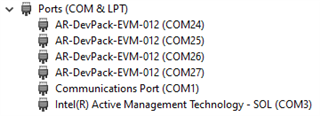
I've recently received the DCA1000 to evaluate the AWR6843 ISK mmWave Evaluation Module. I've been trying to follow this Quick Start Guide and have downloaded all the development tools and software it recommends for Windows 10. After getting to step 6, I am able to see all four AR-DevPack-EVM-012 COM ports but the XDS110 Class Application/User UART COM ports are not visible under Device Manager. I followed the Note about this issue on the next page and downloaded the latest version of the EMUPack drivers. After still not seeing the XDS110 ports, I attempted to install an earlier version of the drivers with no luck.

Using mmWave Studio, I seem to be able to issue a board reset shown by a flash of LED D5 on the AWR6843 ISK, but am unable to connect to it. I presume this to be because of the absence of XDS110 debug COM ports but I am not sure.

Any help is appreciated.

  • Hello Mitchel,

    Please refer to the below snippet from the following user guide: 60GHz mmWave Sensor EVMs (Rev. D) (ti.com)

    Referring to the attached figure above, Rev C and Rev D version of XWR6843 boards (ISK/ODS) have CP2105 USB to UART chips present, hence one need to use the following drivers instead of XDS110 : 

    https://www.silabs.com/products/development-tools/software/usb-to-uart-bridge-vcp-drivers

    Regards,

    Ishita

  • Unfortunately after many attempts uninstalling previous XDS110 installations and reinstalling the drivers you recommended, I have been unable to get the board to connect through mmWave Studio, receiving the same error as before:

    [RadarAPI]: Error: Connection failed: Calling_ConnectTarget returned 3

    My ultimate goal is to be able to interface this product with a desktop computer to process data from the AWR6843 in real-time. I recently had success with the mmWave Demo Visualizer and was hoping I would be able to parse the data stream on the UART Bridge: Standard COM Port with a Python script. However, I was unable to find documentation pertaining to the format of this data stream.

    What is your opinion on the best way to go about obtaining real-time data from the AWR6843? If it is using the configuration values provided by the mmWave Demo Visualizer, do know where I would be able to find documentation on the format of this data stream?

    -Mitchel

  • Hello Mitchel,

    - Can you send a snippet of your Device manager window? I want to see the available COM ports when you connect both the boards. Also highlight the COM port number you're selecting for connection with Studio. Ensure that the COM port used is not being used by any other application. 

    - Now coming to your application of obtaining real time data from the AWR6843 device, please note mmWave Studio is only architected for offline processing. You can refer to my response in the below thread : 

    (+) DCA1000EVM: DCA1000EVM - Sensors forum - Sensors - TI E2E support forums

    Other than that, you could also capture data using DCA1000 by programming "infinite frames" i.e. num frames = 0; and then for every subsequent file captured, you could simultaneously process it on MATLAB or using python (this is based on the fact that after 1 GB of capture, the DCA1000 EVM will start capturing the data into another file. Each subsequent file will have the test “Raw_n” appended to the user given filename where n is a number starting from 0). Although this will technically be a delayed version of "real-time", but can be seen as an alternative. 

    - Coming to the data format of the captured data, please refer to the below document : 

    Mmwave Radar Device ADC Raw Data Capture (Rev. B) (ti.com) (Data format of IWR6843 is analogous to AWR6843) 

    Hope this gets you the required information. Let me know your findings on the studio connection issue. 

    Regards,

    Ishita

  • Hello,

    Thank you for your advice regarding real-time data capture. I will explore the methods you recommended.

    Below are the available COM ports when connecting the device via the RADAR_FTDI port as the Quick Start Guide advises:


    Only when connecting to the micro USB port on the AWR6843 itself (used for the mmWave Demo Visualizer), I get the COM ports you referred to:

    After taking steps to ensure none of the ports were in use by other processes and trying each port individually, none of the 6 COM ports connect to mmWave Studio.

    -Mitchel

  • Hello Mitchel,

    You need to use COM 30 in this case to connect with RS232 for mmwave studio connection. 

    Are you using the AWR6843ISK device in standalone mode or with mmWaveICEboost? I am not able to understand your physical setup and connections. 

    I would suggest following the steps in the attached user guide :

     1665.mmWave_sensor_raw_data_capture_using_DCA1000_xwr6843.pdf

    This has all the hardware and software steps captured nicely for data capture specifically with XWR6843 device. 

    Regards,

    Ishita