This thread has been locked.

If you have a related question, please click the "Ask a related question" button in the top right corner. The newly created question will be automatically linked to this question.

IWR6843AOP: IWR6843AOP and IWR6843

Part Number: IWR6843AOP
Other Parts Discussed in Thread: UNIFLASH,

Hello everyone,

We are working with IWR6843AOP model chip. 

We designed our board with this chip. We are testing our design. We are programming the flash successfully in programming mode (SOP:101). And after that we should pass the functional mode (SOP:100) and reset the chip. We are making this steps but the chip run into error.

After programming we see 1.4V on 1p4V_APLL pin but we could not see 1.4V on 1p4V_SYNTH pin. We could not solve this problem. These two pins are connected pmic_1.8V inside of the chip. Chip gets 1.8V inside of it because 1p4V_APLL is 1.4V, so internal LDO is working for 1p4V_APLL.

And another interesting part is, we see 1.0V on Vout_PA pins. According to bring-up guidelines of chip, this step is coming after PLL and SYNTH blocks' feed.

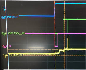
We know that we are initialize it successfully according to this image which is taken from Hardware Bring-up Guidelines of chip. We see same signals characteristics on nRESET and WARMRESET pins as this image when we are starting the chip. Its mean chip is initialized successfully.

Someone get this same problem 2 years ago and wrote it is solved. But we cannot see how they solve this problem.

Could anyone help us for this problem? Why we cannot see 1.4V on 1p4V_SYNTH pin, and why our chip runs into error when we get functional mode and reset it.

Thanks...

Taha

  • Hello

    How have you noted that the flashing step was successful?

    Would  you be able to check the flash clock during both the flashing and functional mode.

    Thank you,

    Vaibhav

  • Hi Taha,

    This thread has been open for a while so I will mark it as resolved. If not, provide feedback to Vaibhav's questions below to re-open for further debug?

    Thanks,

    Eben.

  • As you can see in screenshot of uniflash page, we can programming the flash. We programming the QSPI flash and we get "Program Load Complated Succesfully" message. And we tried what did u ask. We investigate clk and data pins of qspi flash via oscilloscope. We see clear clock and data package. After programming the flash, we change the SOP configurations and reset chip for functional mode. And when we change the SOP mode for funtional mode: 101 and reset the chip, it run into error, pull down the NERROR_OUT pin and blink the led. After taking functional mode and reset chip, it run into error and we cannot observe clock on qspi flash CLK pin.

    In all these steps the problems are still exist and we could not measure 1.4V on 1p4V_SYNTH pin, and why our chip runs into error when we get functional mode and reset it. And we cannot collect any data, we cannot observe anything via MSS_Logger pin on mmWave Studio tool by TI.

    Thanks...

  • Hello everyone again...

    We are currently developing a project with this chip. We can't find any help on the subject.

    Is there anyone who can direct us to someone competent about this chip? 

    We are programming the flash successfully in programming mode (SOP:101). And after that we should pass the functional mode (SOP:100) and reset the chip. We are making this steps but the chip run into error. And we cannot see 1.4V  1p4V_SYNTH pin. Probably we cannot  wake up RF layer of ship.

    We need help for our problems.

    Thanks...

    Taha

  • Hi Taha,

    I am following up on this

    In your first post, you mentioned someone else had this problem and marked it as solved. Can you share me the link to this?

    Thanks,

    Eben.

  • Hi Ebenezer,

    Could you find something? You asked me the link, and I send you, but as I said before they did not explain how they solve the problem.

    Is not there anyone can help us for this problem?

    Thanks..

  • Hi Taha,

    Can you double check if the flash device you have is supported? You can refer to Table 2 in this document:

    https://www.ti.com/lit/an/sprach9b/sprach9b.pdf

    Writing to the flash device is done in single SPI mode but reading from it is done in quad SPI mode only. Depending on the flash device you have, you may need to enable quad SPI mode externally.

    Thanks,

    Eben.

  • Hi again Ebenezer,

    We have already checked it. Actually when we design this board we have examined the IWR6843AOPEVM module documents and design files.

    TI used MX25R1635FZUIH0 model flash. And we used MX25R1635FM1IL0. They are similar, just our flash have soic-8 package.

    And we watched pins of flash with oscilloscope. As you said, when we writing, it uses single SPI mode. And we see approximately 80MHz CLK signal on 6th pin of flash when we writing. These are OK. After that, we get chip SOP:101 (functional) mode and reset chip. Meanwhile we watched flash clock again and we see clock packages and 80MHz signal again. We can say that, chip starts normally, and it passes some initialize steps to send flash CLK. Chip starts to communicate with flash first, as you can see there is 80MHz clock, but communication is closed after chip run into error.

    But maybe we should focus, why synthesizer  LDO is not working when PLL is working? We see 1.4V on 1p4V_APLL pin but cannot see 1.4V on 1p4V_SYNTH pin. What do you think about it?

    You can look our flash scheme and oscilloscope screenshot when we start chip in functional mode.

    So, we think the problem is not coming from flash. 

    What else do you think this error could be caused by?

    Thanks...

    Taha.

        taken meanwhile in functional mode start-up

  • Hello again,

    We cannot solve our problem. And no one could not help us yet. 

    We are currently developing a project with this chip. We can't find any help on the subject.

    Is there anyone who can direct us to someone who competent about this chip or IWR6843AOPEVM module?

    Thanks

    Taha..

  • Hello Taha,

    We have seen problems with MX25R1635FM1IL0 flashes in past, Please see the post below. 

    https://e2e.ti.com/support/sensors-group/sensors/f/sensors-forum/804147/ccs-iwr6843-custom-pcb-will-not-load-programs/2976302#2976302

    Please try to use the same flash that is present in the reference design MX25R1635FZUIH0. 

    Also, 1p4V_APLL would be powered up by the Bootrom finishes the loading, However 1p4V_SYNTH is used for the powering up the RF section. This would be enabled only after the RF INIT APIs are being executed by the Master system application code. 

    In this case before Flash code is being loaded into MSS memory, there is an error detected (Possibly flash reading did not happen successfully),  If there is error in reading the flash code then NERROR would be asserted. All these signature points to incompatibility of the flash device. Please replace the flash with the reference design flash. 

    Thanks and regards,

    CHETHAN KUMAR Y.B.