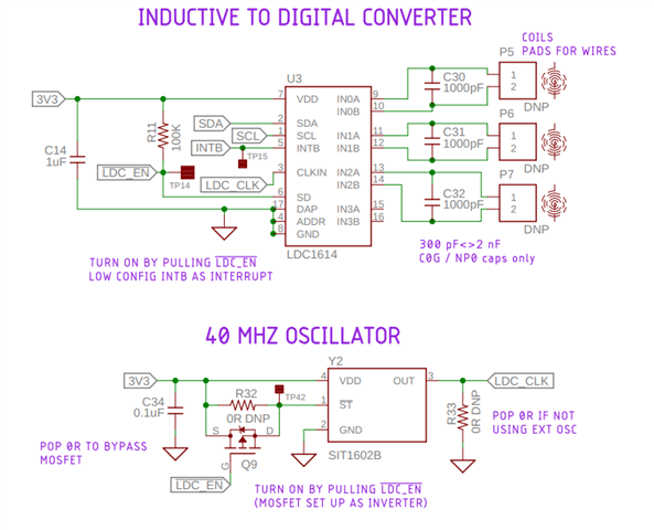
This thread has been locked.

If you have a related question, please click the "Ask a related question" button in the top right corner. The newly created question will be automatically linked to this question.

LDC1614: Drift in raw values over time, and between restarts

Part Number: LDC1614

Setup:

LDC1614

4 layer, 10mm coils

Target is a stainless steel braided wire

Target distance is less than 1x coil diameter

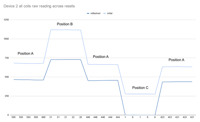
As the title suggests, I'm experiencing a drift over time in the raw values collected by my LDC1614 sensor. In the test, I held the target at position A, then moved to position B, back to position A, position C, position A. These are fixed positions for the purpose of this test. The test duration was about two minutes from the first reading to the last, and then the firmware was flashed, and the test was repeated. The vertical axis is the raw sensor value, subtracting the minimum from the range.

As the graph shows, there's a relatively significant change in the raw values read from the same position over a two minute period. There's also a significant change in raw values read between firmware flashes. 

Is this normal activity? It's making it challenging to measure real-world distance to target, as our calibration values seem to lose meaning over time and between flashes/restarts. Could it be an issue with our reference oscillator?

  • Jordan,

    You mentioned the target is made of braided wire.
    Do you get the same drifts if you use a solid steel target with the same dimensions as your braided target?
    What is the placement accuracy of the target?

    Regards,
    John

  • The position accuracy is quite repeatable. I've attached an image. A small carabiner is at the end of the braided wire and is attached at the intersection points shown in the image. The sensors are fixed to the base of the wire.

    I haven't tried another target, but the wire is 49 strand, so the cross section is nearly uniform. Also the data doesn't show any randomness as it would if the surface of the target was impacting the measurements. The data shows a continuous trend over time.

  • Jordan,

    We advise the use of  solid targets because they support the formation of eddy currents, which is a key consideration in inductive sensing. The only time we advise the use of something like a mesh structure is to minimize parasitic eddy currents in sensor shields/ground planes to minimize EMI. More detailed info on that can be found in an app note available for download here.

    My guess is the screens in your target make eddy currents - and therefor the sensed inductance and resulting device output - very sensitive to the target placement (in {x,y,z}) and rotational orientation with respect to the sensor.

    One way to test this hypothesis is to re-run your experiments with a solid conductive target with the same approximate dimensions as your grid target. If you try this, and you se the same behavior, we can move on to some other experiments to track down the problem.

    Regards,
    John

  • I hadn't tested a solid target, which I can do to rule this out. The individual strands aren't coated in anything, so there's nothing non-conductive between the strands and shouldn't act as a mesh (to my understanding). Also I tested the multi-strand wire with the EVM board and the data didn't display the same drift, or the same dynamic range in the sensor values. This is the main reason I feel I'm missing something either in configs, or somewhere else.

  • Jordan,

    Your comment about testing the multi-strand wire with an EVM caught my attention.
    I assumed that's what you were doing when you saw the drift. My bad. Sorry about that.

    What PCB, configuration and ref clock are you using for your testing?
    Regards.
    John

  • It's a custom PCB, 4 layer, running a LDC1614 with three coils. We adhered to EMI reduction techniques in the data sheets. Reference clock is in the screenshot above along with the LDC schematic.

  • Jordan,

    If a solid target doesn't change the drift/shift you see, then the next step would be to see if the clock drift and/or jitter is the cause.
    It might also be worth confirming the waveform on the sensors are within the suggested frequency and voltage ranges.

    Regards,
    John